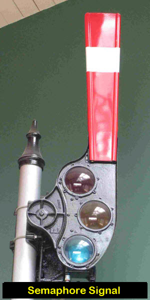
RAILFAN GUIDES HOME RAILROAD SIGNALS HOME The photo at the top of the page was
taken in 1974, on a trip to New Haven CT on the Northeast Corridor via
Amtrak. During this period, Amtrak was still using heritage
fleet cars, and you could easily take pictures out of the vestibules. This picture was taken somewhere in the Bronx.
So what is a semaphore, and what makes it different than other signals?
Semaphore signals revolutionized and standardized the railroad signal industry at the same time.
Compared to earlier signals, they provided the railroads with a superior method of transmitting track conditions to the engineer
A semaphore signal is one by which the aspect is given by the position
of a blade (during the day), and by colored light at night. The
fact that the semaphore signal uses a moving blades to convey information
to the engineer sets it apart from most other signal types (except for
maybe Ball and Tilting Target signals, which also conveys their
indications by way of a moving device/indicator).
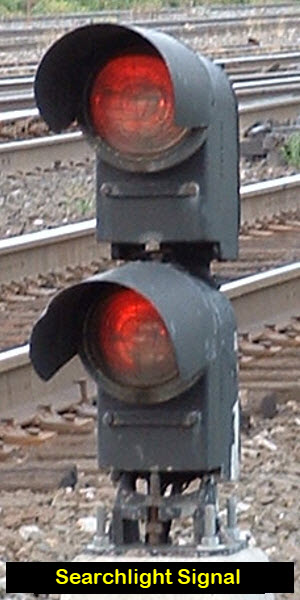
For comparison purposes, below is a quick rundown of the main signal types seen across America.
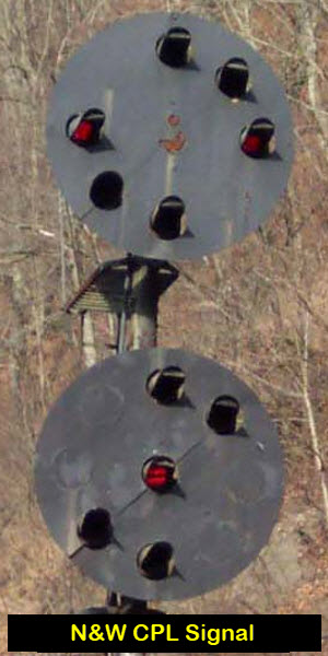
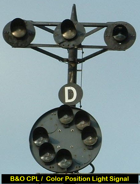
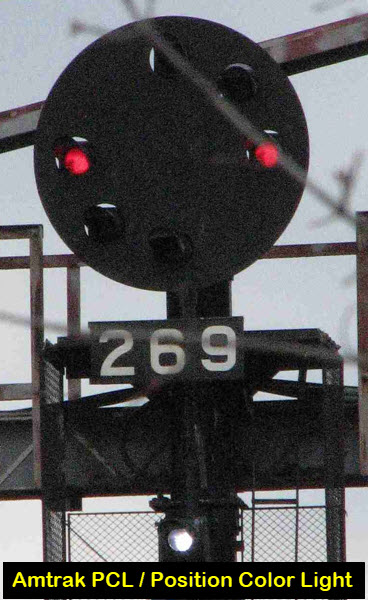
The N&W CPL and Amtrak PCL signals are adaptations of the Pennsy PL signal.
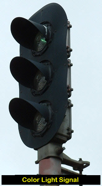
The "trilight" signal is a special version of a color light signal -
professional signal maintainers call them color light signals, and purist signal
fans hate the term and will call you a poser if you use it. Most railfans
use the term "trilight" to differentiate between it and a standard 3 aspect
color light signal.
Semaphore signals were originally illuminated by a kerosene lamp.
Once tungsten filaments were perfected, railroads were quick to replace
the kerosene lamps with electric bulbs. Those reading this tutorial
and belong to the Railway Signaling group (which used to be on Yahoo Groups,
but has now moved over to GROUPS.IO), are well aware that early semaphore
glass lenses actually look bluer than green. This is due to the fact
that the light source of the kerosene lamp contains more yellow and green
than that of an incandescent lamp, and thereby filters the light to a green
color... but use that same lens with a bulb, and the resulting color will be much bluer!
According to one source, the semaphore was patented in the 1840’s by John James Stevens.
1a) In FRA rule 236.23, semaphore aspects and indications are shown by:
1) The position of the semaphore blade,
2) The color of lights,
3) The position of the lights,
4) The flashing of the lights, or,
5) Any combination thereof.
1b) The indications may be qualified by:
1) A marker plate,
2) A number plate,
3) A letter plate,
4) A marker light,
5) The shape and/or color of the semaphore blade, or,
6) Any combination thereof.
If you happen to have access to any of the old catalogs
from the early 1900’s, they are most informative as to the
wide variety of semaphore signals that used to be available,
compared to what we are used to today with color light signals.
Additional Resources and Information:
Jersey Mike
Denver Todd
Scot Lawrence
Mark E
Mike Stellpflug
Brian Sellers
Google n Google Images
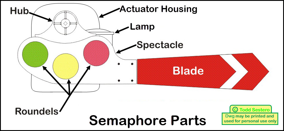
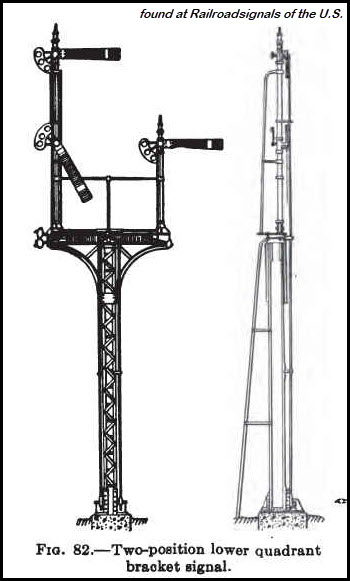
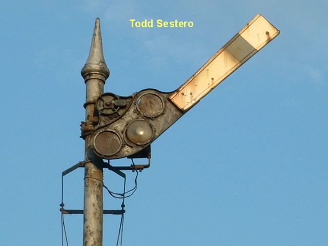
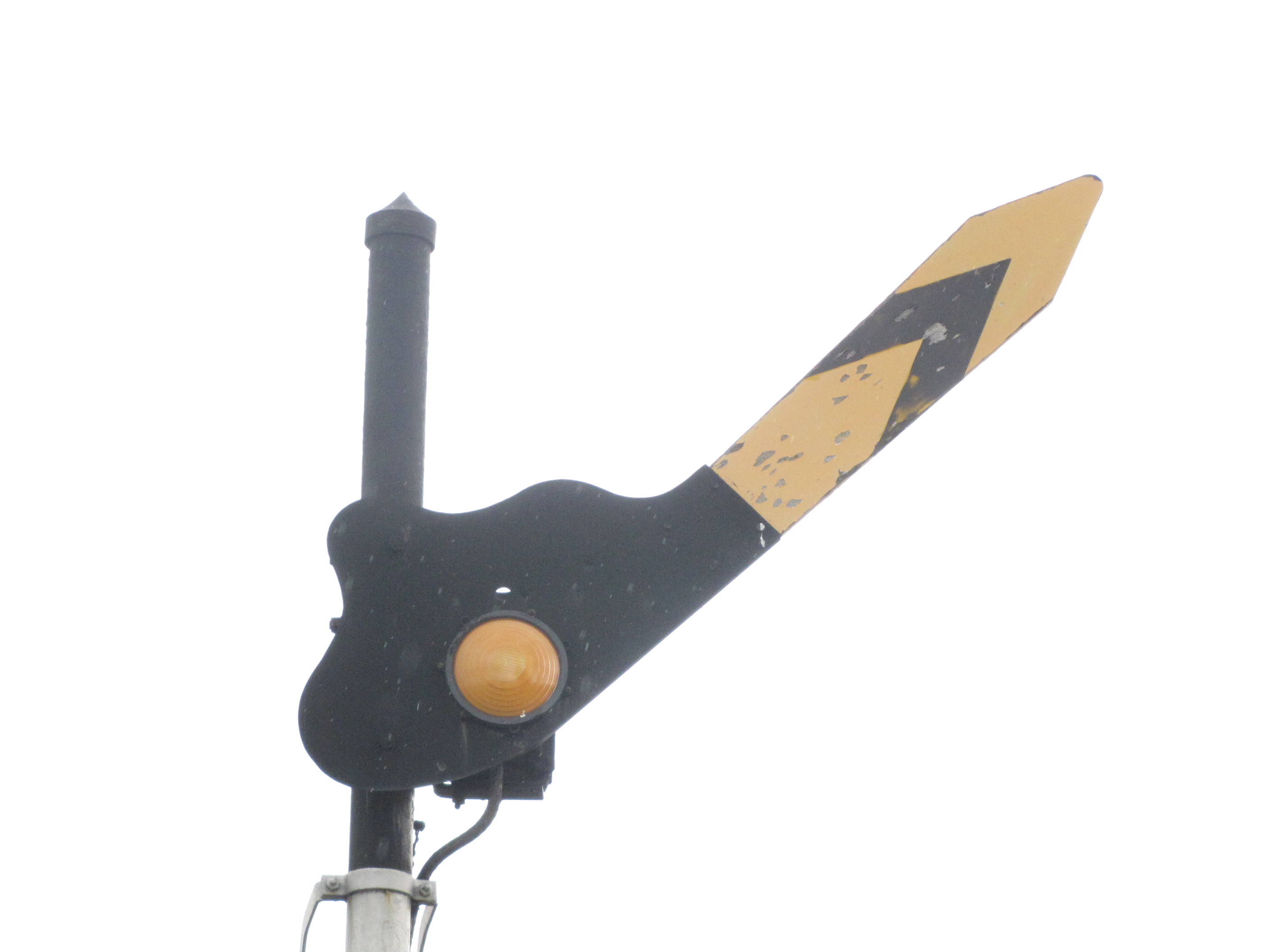
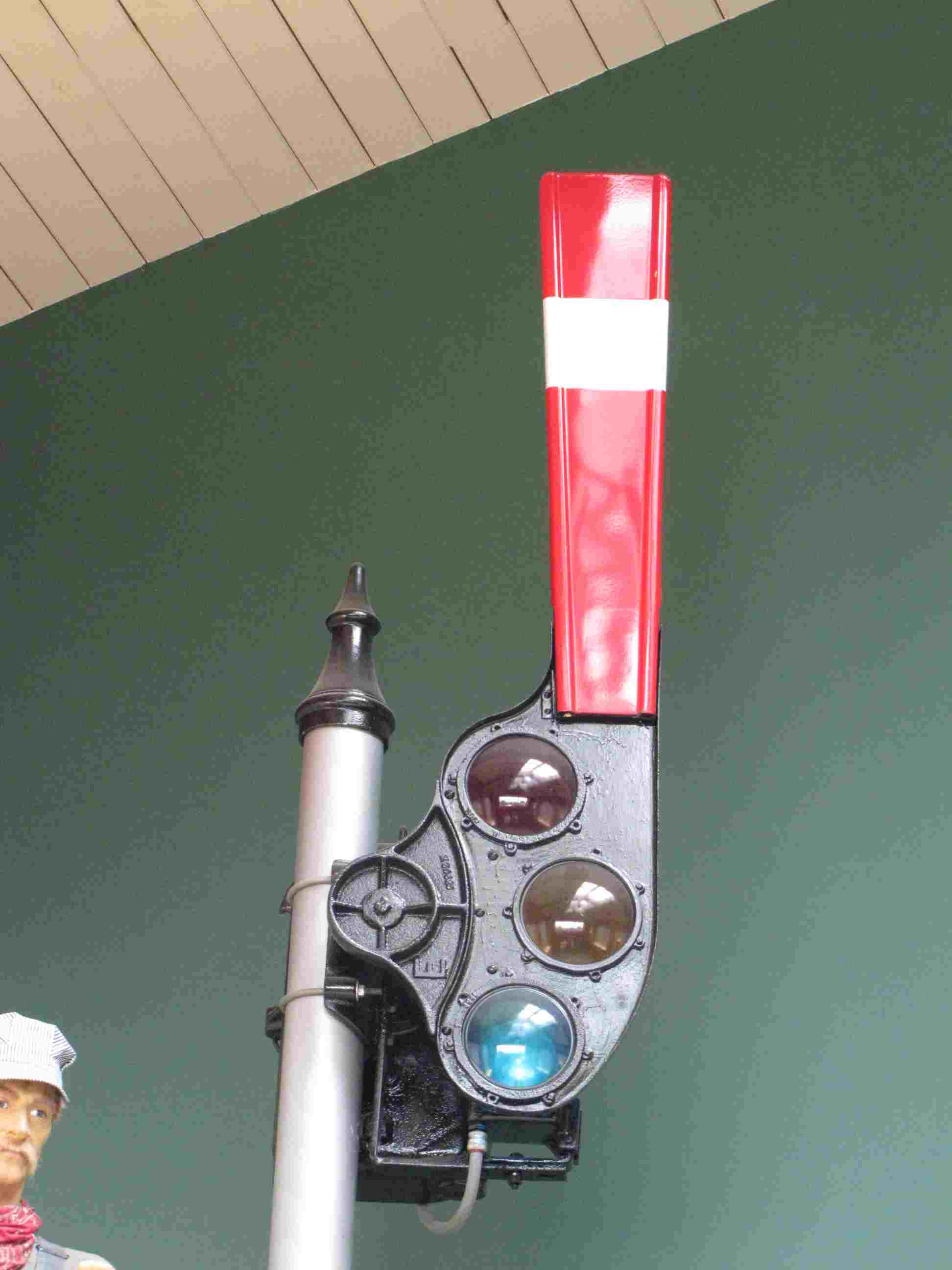
2a) The major parts of any semaphore are:
1) The blade,
2) The lenses, or to be more correct for semaphores, roundels,
3) The spectacle, this is what holds the roundels,
4) The lamp,
5) The actuating mechanism, and
6) The housing.
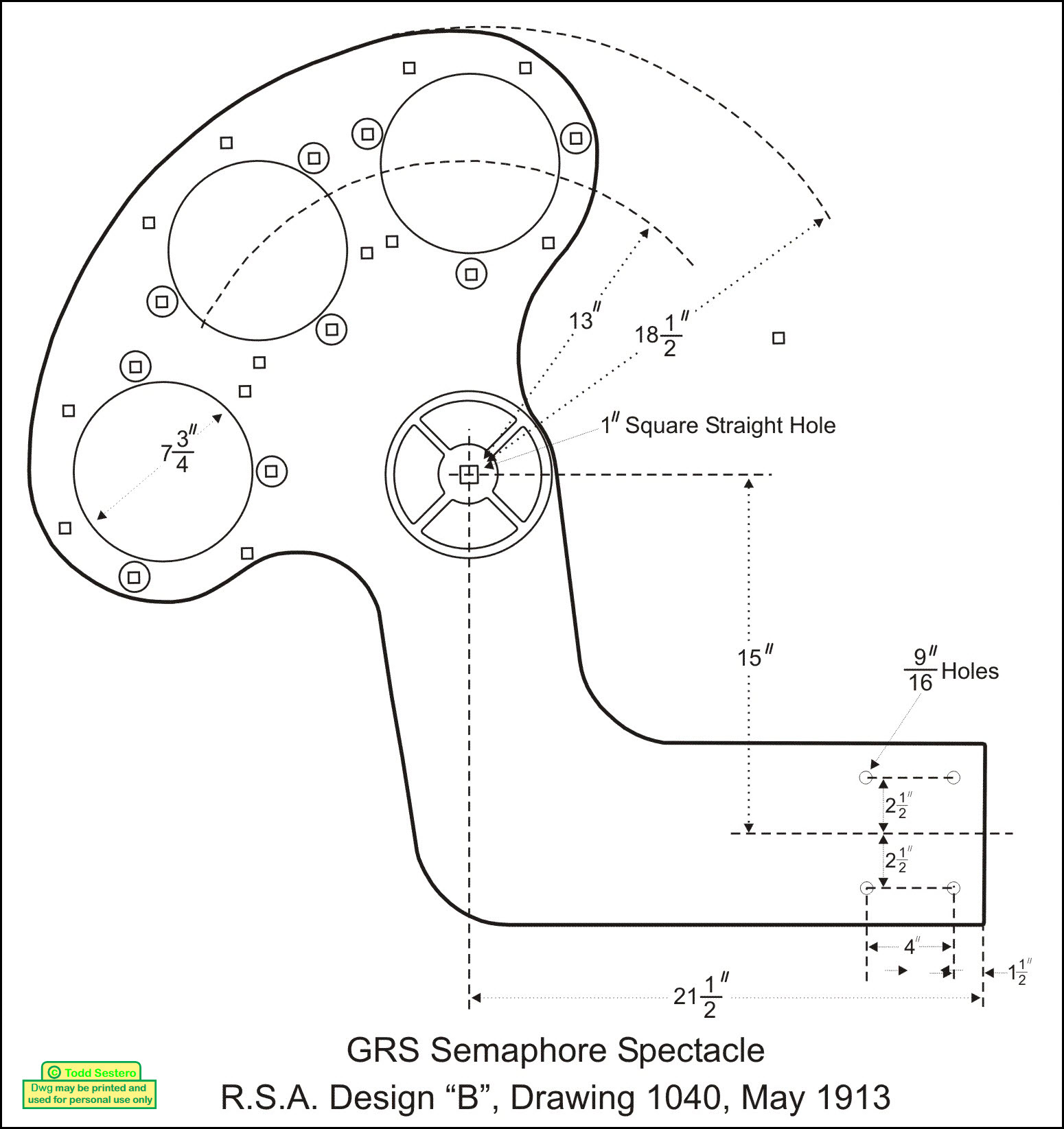
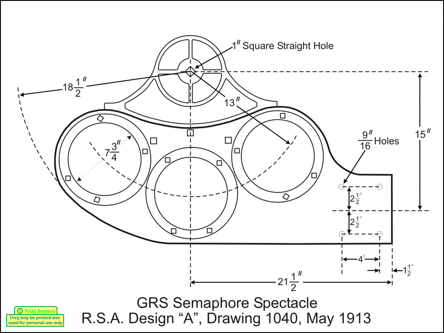
Picture 1 and 2
Typical Upper Quadrant Spectacles - Standard designs, redrawn from a GRS catalog.
To see what one reader used the above drawings for, check out this
YouTube Video on
building your own scale model semaphore using an Arduino.
The spectacle mounts to a shaft, which is usually one inch square at
the end to mate with a like hole in the spectacle.
In mechanically or base-of-mast actuated semaphores sitting at the top of a mast, the shaft rides
in a fitting, sometimes with a set of bearings, and the fitting mounts to the mast.
There is a rod on the "far side" of the fitting, which goes down the pole to an
actuating device.
With top-of-mast or dwarf installations, the shaft comes out of a housing, which contains the
actuator. Top-of-mast housings mounts on the mast, and supports the semaphore.
Dwarf installations would have the housing resting on a concrete base, or
brackets mounted to a concrete base.
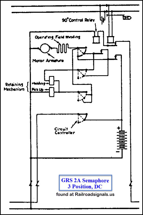
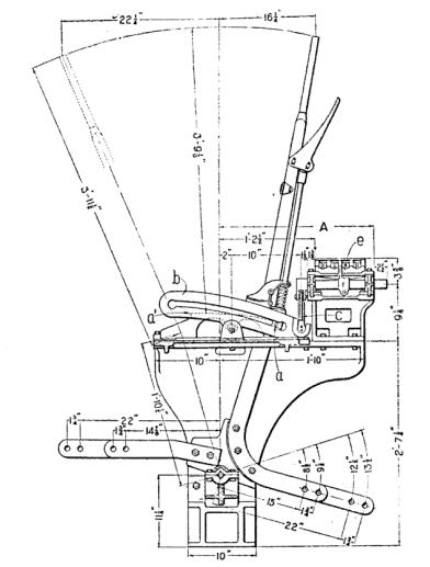
This section will go into the
operation of how they make the semaphore blade go up and down. I have used
an upper quadrant GRS type 2A semaphore for this discussion. The schematic comes from a
GRS service booklet for this type. My schematic is taken from a later
version of the GRS type 2A, shown in the left drawing below. The GRS
schematic below does not show the snubber resistor circuit. On the right is a
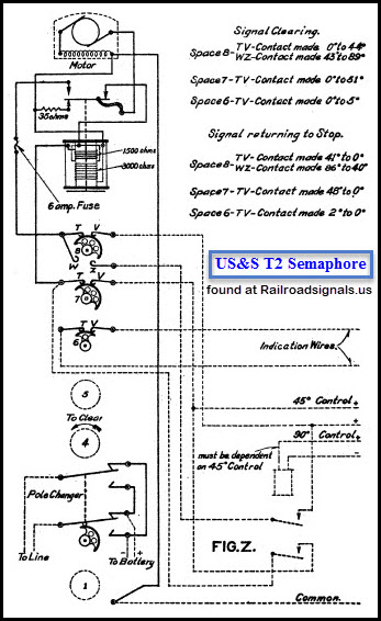
schematic of a US&S type T2 semaphore.
4a) Even though they appear on -my- drawing, let's go over the initial conditions so we know where we are:
1) For the sake of our discussion, we are describing an upper quadrant, 3 position semaphore.
2) The train is traveling from left to right, and is currently in Block D.
3) The track batteries are not shown.
4) The semaphore affected by this circuit is the "green" one on the left, at the end of Block A, protecting Block B.
5) The semaphore itself (exclusive of the track circuit) operates from 12VDC.
6) Although it is not standard convention for relays, they are shown in their "picked" position (energized).
7) We have a control signal coming from the semaphore circuit in Block C.
8) We have a control signal feeding Block A.
9) The Signals are set up as 3 block intermediate signals, with no interlocking to complicate the relay logic.
10) And last but not least, the semaphore is at green, because neither Block B or Block C are occupied.
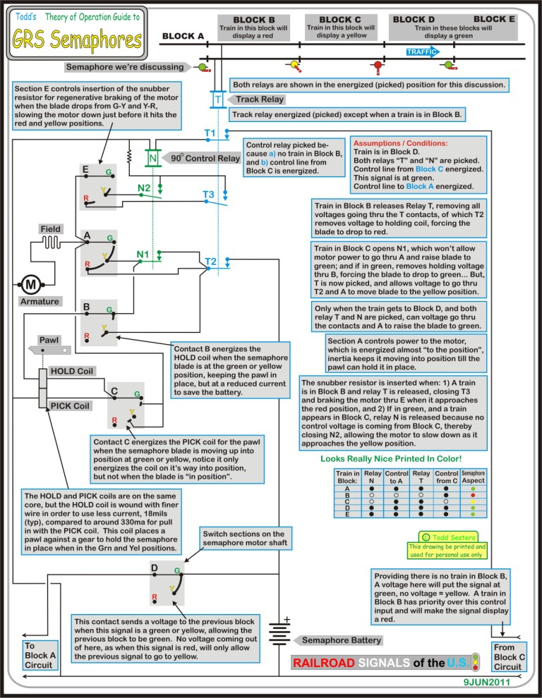
Real quickly, the track circuit is the foundation of any signal
circuit, without it, we have no way to tell if a train is in a block.
4b) A basic track circuit has:
1) A battery as the source of voltage,
2) A series limiting resistor to set the loop current and adjust the pick-up point of the relay,
3) The track itself, and,
4) A track relay.
With no train in the block, the battery (placed at one end of the block) voltage is put
out onto the tracks, the tracks carry the voltage down to the opposite end of
the block to the relay, where the the relay becomes energized. When a
train enters the block, the wheels and axles shunt, or shorts out the circuit
so the relay is no longer energized. With the relay de-energized, the
relay contacts are opened. This gives us the failsafe
operation we need for safety - this way, if the track is broken, or the battery
dies on us, the contacts will be open, and force the signal to a red aspect.
So let's do GREEN first, since my schematic is set
up for that condition...... With the train two blocks ahead
of us, we have a green aspect on our semaphore. That means we have a 12V
control signal from Block C, which energizes relay N since contacts T1 are
closed because relay T is picked. The local battery is fed thru contact
T2, which is also closed because relay T is energized. With 12V
being able to reach contact A, it feeds the motor thru the R contact, raising the blade to
the yellow position. Since contact N1 is also closed (because relay N is
picked), when the wiper of A gets to Y, there is also voltage there waiting to keep the motor
running and raise the blade to the green position. Hope you followed that.
Contact section D outputs a voltage to the previous block if our signal is
showing either a green or yellow. This allows the previous block to
display a green if all other conditions allow for it.
Now let's see what happens if a
train is in Block C. Since the track relay T for this block is now
not energized, it will force the yellow semaphore on my drawing to red.
Because of this, Contact D is now positioned so that no voltage goes thru and
there is no output to the previous block. Subsequently, relay N of the
previous block (the signal of discussion) is not energized. Because of
this, contact N1 remains open, and when the wiper gets to position AY, there is
no voltage there to energize the motor to take the blade into the green
position, and our semaphore is at YELLOW. If,
and only when, the train in Block C moves on to Block D, will the voltage
re-appear at AY to move the blade into the green position.
A RED
condition is the easiest to describe, since track relay T is not energized
because of a train in Block B. This means both contacts T1 and T2 are
open. With T2 open, no voltage can get to contact section A to energize
the motor and take the blade into the yellow or green position. Also
because T2 is open, it removes any voltage from the PICK and HOLD coils (thru
contact B), which would release the pawl holding the blade in either the green
or yellow position, allowing the blade to fall back to the red position.
Also, contacts N2 and T3 are closed, and would apply braking to the motor when
the blade approaches the yellow and red positions.
Picture 6
My circuit of a GRS semaphore with an explanation of how the thing works.
There have been a number of discussions over the years
on several groups as to how semaphore signals are referred. A lot of us
"younger" guys have a tendency to call it a signal head, as is
commonly done with color light signals. Purists and "old timers" are
inclined to call them arms, but then, the purists also want to call any
signal head an arm. With all of the signals guys I personally know, and
other I have come across, none of them use the term arm.
A couple of emails from June 2011 follow:
This is the email that started the discussion: People and animals have "heads."
Signals have "ARMS."
As in "top arm," "middle arm," "bottom arm" of a signal.
The nomenclature goes back to the early semaphore days.
Sorry to be the purist.
-- abram
I then sent out an email across several of the signaling groups,
asking: Are signals today called HEADS, or ARMS as this gentleman prefers?
One reply said: Don't know about today, but back when I worked in the signal department
they were called heads both in the signal engineers office and out in the
field. An additional term heard when carrying one up a signal ladder was "heavy
X&#*%!" :-).
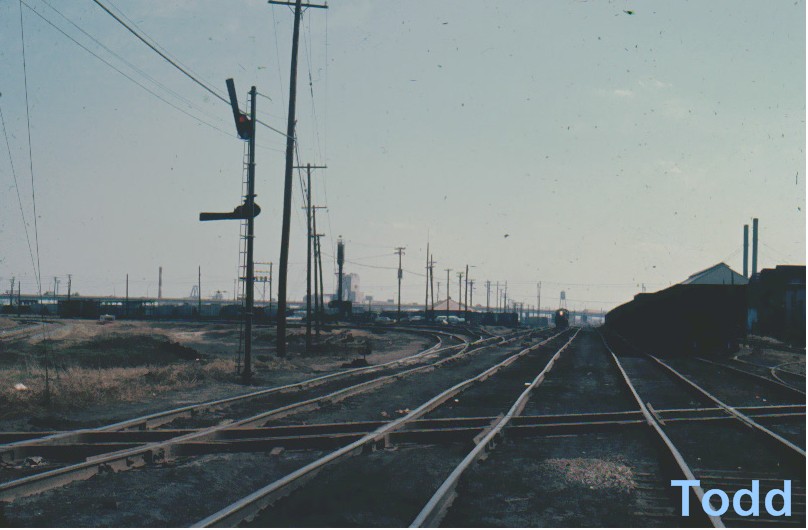
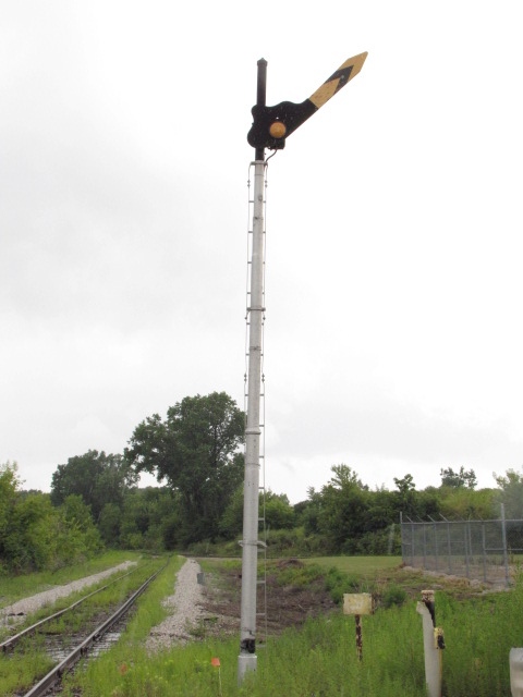
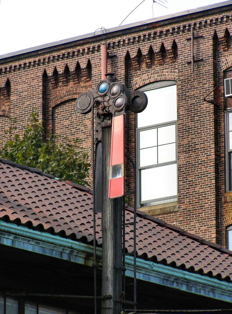
Semaphores took a number of forms. The most obvious difference compared to
other signal types, is the way they displayed their indications, with
the blade moving either up or down from the horizontal position.
The horizontal position was always a red aspect, indicating STOP.
If the blade moved down from the horizontal, it was a lower
quadrant semaphore.
If the blade moved up from that position,
it is called an upper quadrant semaphore.
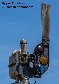
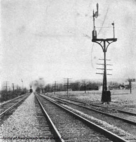
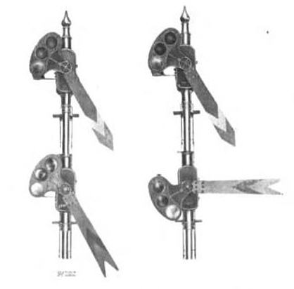
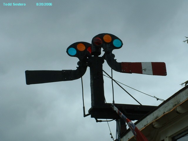
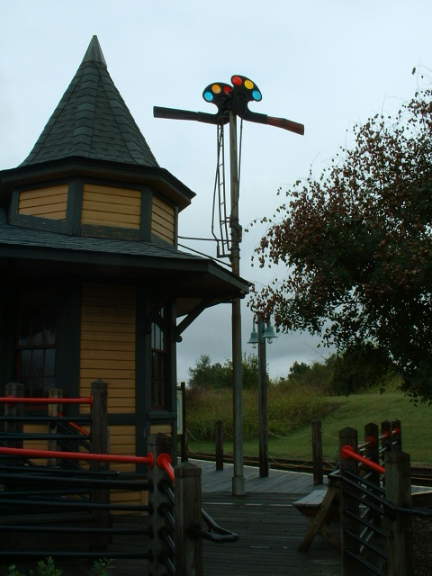
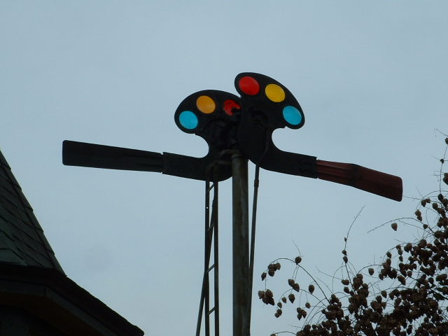
The picture at the top of the page shows an upper quadrant semaphores with
two arms/heads. Upper quadrant semaphores came about around 1900.
As we will see a little further down on the page, semaphores were actuated by
mechanical, pneumatic, electro-pneumatic, or electrical means.
They can be further divided by the location of the actuating mechanism. For manually
operated semaphores, the operating lever could be at the base of the mast, on an
adjacent platform, or in a remote room (or tower). For power operated
semaphores, the control point could be the same as for manual semaphores, but
the actual operating mechanism, be it a motor or whatever, was located at either
the base of the mast, or up on the pole, where the semaphore spectacle and blade
mounted directly on the gear shaft.
Like most other signals semaphores came in both the high signal variety, and dwarf versions. And when speaking of
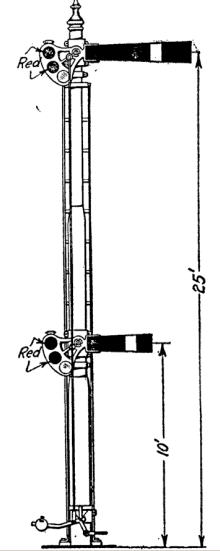
semaphore signals, high signals were really high, often with a single arm (or the
lower arm of a dual or triple indicating signal) being 17 feet (or more) off the ground.
These differences are covered in section 7 in greater detail.
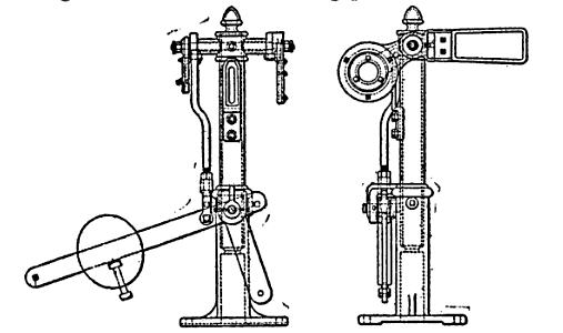
6a) Quick review - Semaphore signals came in a wide variety of forms, and to my knowledge, more than any other type of signal:
1) Semaphore signals could be: *
-- Upper quadrant (Stop is horizontal, clear is up) (left below in picture 1)
-- Lower quadrant (Stop is horizontal, clear is down) (right below in picture 2)
2) Semaphore signals can be:
-- Single (fixed) position,
-- Two position, or,
-- Three position,
3) Blades stopping at either:
-- The 0, 45, and 90 degree positions (Upper quadrant signals), or,
-- The 0, 30 ,and 60 degree positions (Lower quadrant signals), *
4) Semaphores signals can be:
-- High signals or,
-- Dwarfs,
5) They could be mounted:
-- At ground level,
-- On a mast,
-- On a signal bridge,
-- On a cantilever bridge,
-- Or on a building,
6) Semaphores can be:
-- Not illuminated,
-- Illuminated by either a kerosene or incandescent lamp,
7) Related to the illumination thing are the lens colors:
-- Red,
-- Purple was sometimes used in very early signals in lieu of red,
-- Yellow,
-- Green, and,
-- White was used in very early signals before a suitable green lens was perfected.
-- I don't believe any semaphores had a lunar white roundel installed,
8) The blades "ends" could be:
-- Square,
-- Round,
-- Pointed, or,
-- Fishtail, *
9) Blade Sizes
10) Variances in blade color, often relating to their meaning, *
11) Semaphores could be operated by:
-- Mechanical means, either pipes or cables (wires),
-- Pneumatics,
-- Electro-pneumatic, or,
-- Electrical,
12) Powered semaphores can have the power unit/actuator at either the base or top of the mast, *
13) There could be one, two, or three semaphore signals on a single mast for a single indication,
14) Or there could be a combination of signals on the same mast. *
15) Smashboards – a special kind of semaphore
(I believe those variations that are unique to the semaphore, have an asterisk *)
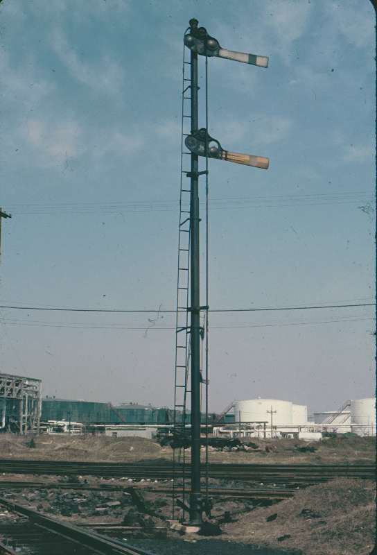
Probably one of the most obvious difference between the types of semaphores is the way
they display their indications, with the blade moving either up or down from
the horizontal position. If the blade moved down from the horizontal, it was a
lower quadrant semaphore. If the blade
moved up from that position, it is called an upper
quadrant semaphore. The picture at the top of the page shows a pair
of upper quadrant semaphores used to give one indication. All of the original
semaphores appearing in the late 1860’s, were of the lower quadrant variety….
upper quadrant semaphores started appearing around 1900.
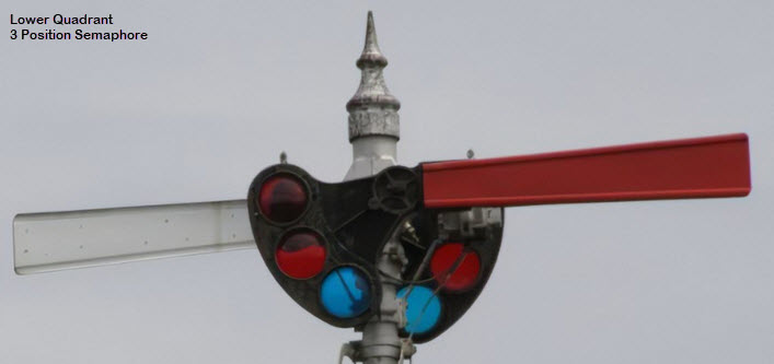
Picture 7 & 8
An upper quadrant semaphore on the left, and a pair of back-to-back lower quadrant semaphores on the right.
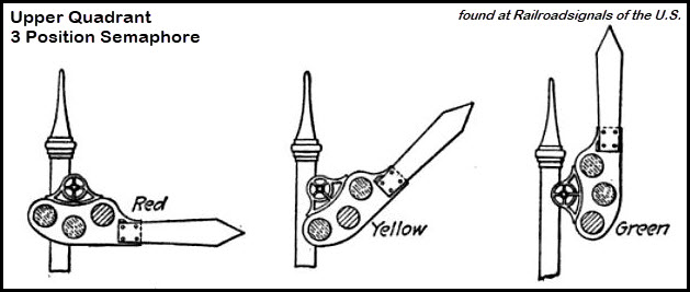
Picture 9
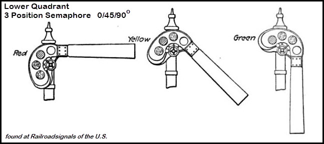
An upper quadrant semaphore shown in it's three positions - lower quadrant semaphores shown below in figures 4 and 5.
7b) Number of Positions
Most, if not all of the early semaphores were only two position signals,
indicating either stop, or proceed/clear. By the time upper quadrant signals
started to appear, the use of three aspects on a semaphore was fairly universal.
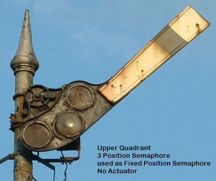
Many semaphores were used in one position only, and permanently
left in the 45, or approach position to serve as a warning for something coming
up, such as a bridge. This was commonly used to give a restricting
indication, and the last surviving semaphore in Baltimore was of this type.
Picture 10
A fixed semaphore. They almost always use a standard spectacle with two of the roundel positions blanked out.
Picture 11
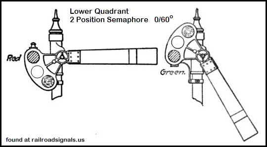
Two position lower 0/60 quadrant semaphore.
Picture 12
Three position 0/45/90 lower quadrant semaphore.
7c) Indexing Positions
Stop was always the horizontal position, which I’m guessing from what I have
read, was a carry over from the beginning of transportation when gates were
put across roads in the horizontal position to stop traffic - preventing
anyone from proceeding any further.
As far as the proceed indication is
concerned, on the early signals, clear would usually take the 60 degree down
position as shown above. Later, when a third aspect was added, approach, it
rested at the 30 degree down position. Some lower quadrant signals also
operated at 45 and 90 degrees.
When upper quadrant signals made their appearance, I believe they were
all of the 0, 45, and 90 degree type – I am not aware of any upper quads
that had stops at 0, 30, and 60.
As the technology of signaling developed,
the concept of failsafe operation became a necessity. Lower quadrant semaphore
signals were not inherently failsafe because, if for some reason, the mechanism,
electricity, air, or the cabling failed, the blade would have a tendency to drop
due to gravity. Because of this, a lower quadrant semaphore giving us a stop
indication, could fall to the approach or clear position, thus allowing the
engineer to pass the signal and head into danger!
It’s interesting to note, that when both
the Pennsy Position Light and B&O Color Position Light signals were developed in
the 1910’s, they used lights to simulate the blade position of an upper quadrant semaphore!
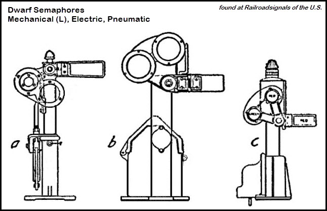
7d) Is It A High or Low/Dwarf Signal?
Semaphores could be found in a full size version high atop a mast, or dwarf versions - a
more "compact" style to be used in yards, on sidings, inside tunnels, or
wherever else there were close clearances that had to be dealt with. Usually,
but not always, the dwarf signals were used for slower speed indications. The
tight clearances in subway tunnels is an example where a dwarf semaphore would
be used as any high signal would be used. When speaking of semaphore signals,
high signals were really high, with a single head (or the lower arm of a dual
or triple semaphore signal) being around 17-30 feet off the ground!
Picture 13
Representative dwarf semaphores.
Picture 14
A mechanical three arm lower quadrant dwarf semaphore drawing I found on an auction website,
they wanted $199 for the thing in a frame!
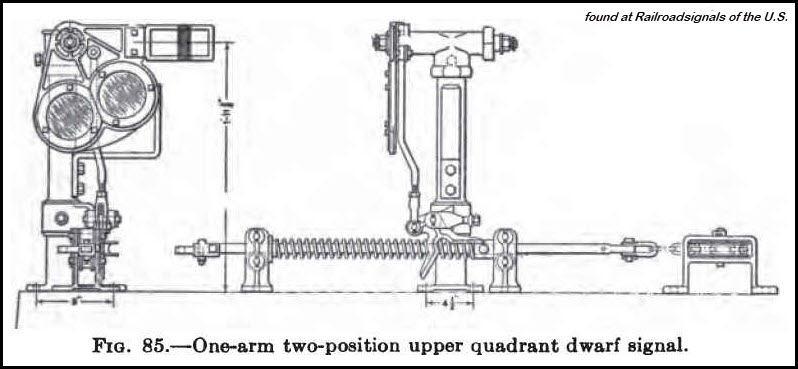
Picture 15
A mechanical two position, upper quadrant, dwarf semaphore.
Picture 16
Drawing similar to the above semaphore.
Picture 17, 18, and 19
Two mechanical type semaphores, one showing the cross section of the ground installation,
and a Hall Style-K high semaphore (R).
7e) Mounting Methods
Like every other type of signal, the semaphore could be found anywhere the
designers wanted to put them: on or close to the ground (as in a dwarf signal);
high atop a pole, where the actuating mechanism may or may not be located “up
there” with the signal itself; on a signal or cantilever bridge with anywhere
from one to three on a mast; on bracket posts; or on the side or top of a building, such as a
tower or station (and used typically as a train order signal, as opposed to a
wayside signal).
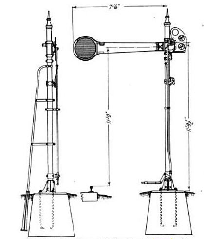
The footings for high signals can be six feet deep or more, and could have as much as
10,000 lbs of cement in the hole to keep the mast upright in the face of high winds.
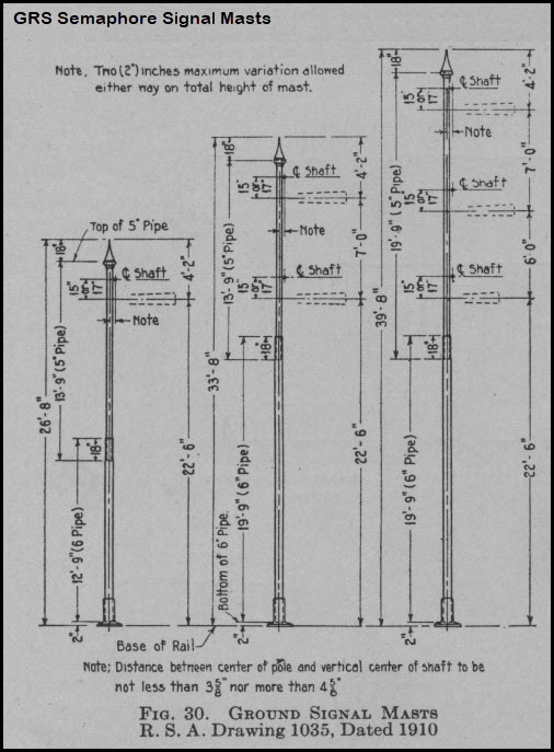
Many ground installations with three semaphores on a single mast would start off with a 7”
pipe in the base, and then step down to a 6” and 5” pipe, roughly dividing the height into thirds.
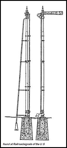
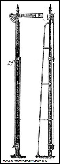
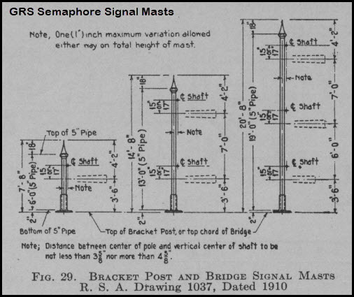
Picture 20 and 21
On the left are masts for "high" signals,
On the right are typical shorter masts for mounting a semaphore on a signal bridge or bracket post installation.
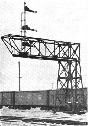
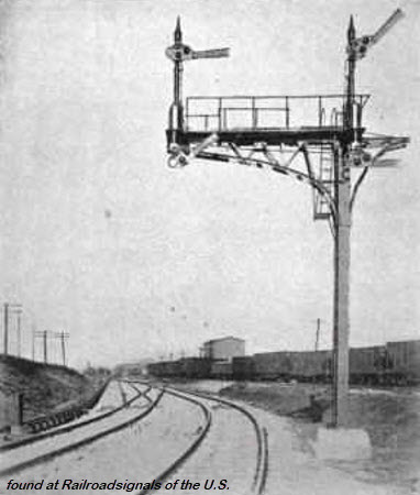
Picture 22 and 23
Two cantilever bridge installations.
Picture 24 and 25
Two bracket post installations:
On the left, a semaphore with a doll post - indicating that the signal is not for the right track,
On the right, a drawing of a dual signal installation for two tracks.
For more information on doll posts, click here.
Picture 26 and 27
Several variations for the installation of train order signals, which
are typically located at either a station or a tower.
Upper quadrant on the left, lower quadrant on the right, both mechanical types.
7f) Let’s Shed Some Light On The Subject – Lighting Methods
When they finally got around to
lighting up the semaphore, they were originally illuminated by a kerosene lamp.
The early attempts at illuminating the signals at night were not very efficient
by today’s standards. The kerosene lamps had an inefficient reflector behind
the wick, and the lenses had no focusing ability at all, so what little light
did manage to make it out of the lamp, was deflected all over the place, instead
of being focused down the track towards the engineer.
Those reading this tutorial who belong to
the -Railway Signaling group- are well aware that early semaphore glass
lenses actually look bluer than green, as we have had many discussions on this
subject. This is due to the fact that the light source of the kerosene lamp
contains more yellow and green than that of an incandescent lamp, and thereby
filters the light to a green color... but use that same lens with a bulb, and
the resulting color will be much bluer!
Many early lamp conversions took the kerosene lamp, and installed a lamp socket where the wick assembly went.
Picture 28
RSA standard drawing for an early kerosene semaphore lamp.
7g) Lenses, AKA, Roundels
Once tungsten filaments were perfected, railroads were quick to replace the
kerosene lamps with electric bulbs because they were much easier to maintain.
When semaphore signals were first illuminated at night, the standard
was white for proceed, yellow for approach and red for stop. Green was not
deployed until a usable green dye for coloring glass became a reality in the
late 1800’s. You began to see green replacing white around 1899. Purple was
also used in dwarf, or slow speed signals for stop in lieu of red, and the
practice continued into the 60’s here in the U.S. Purple is still used overseas
for stop in shunting signals, along with white for proceed.
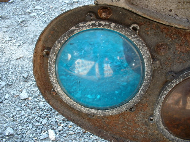
Picture 29
Notice how blue this lens is! This roundel is for a kerosene lamp.
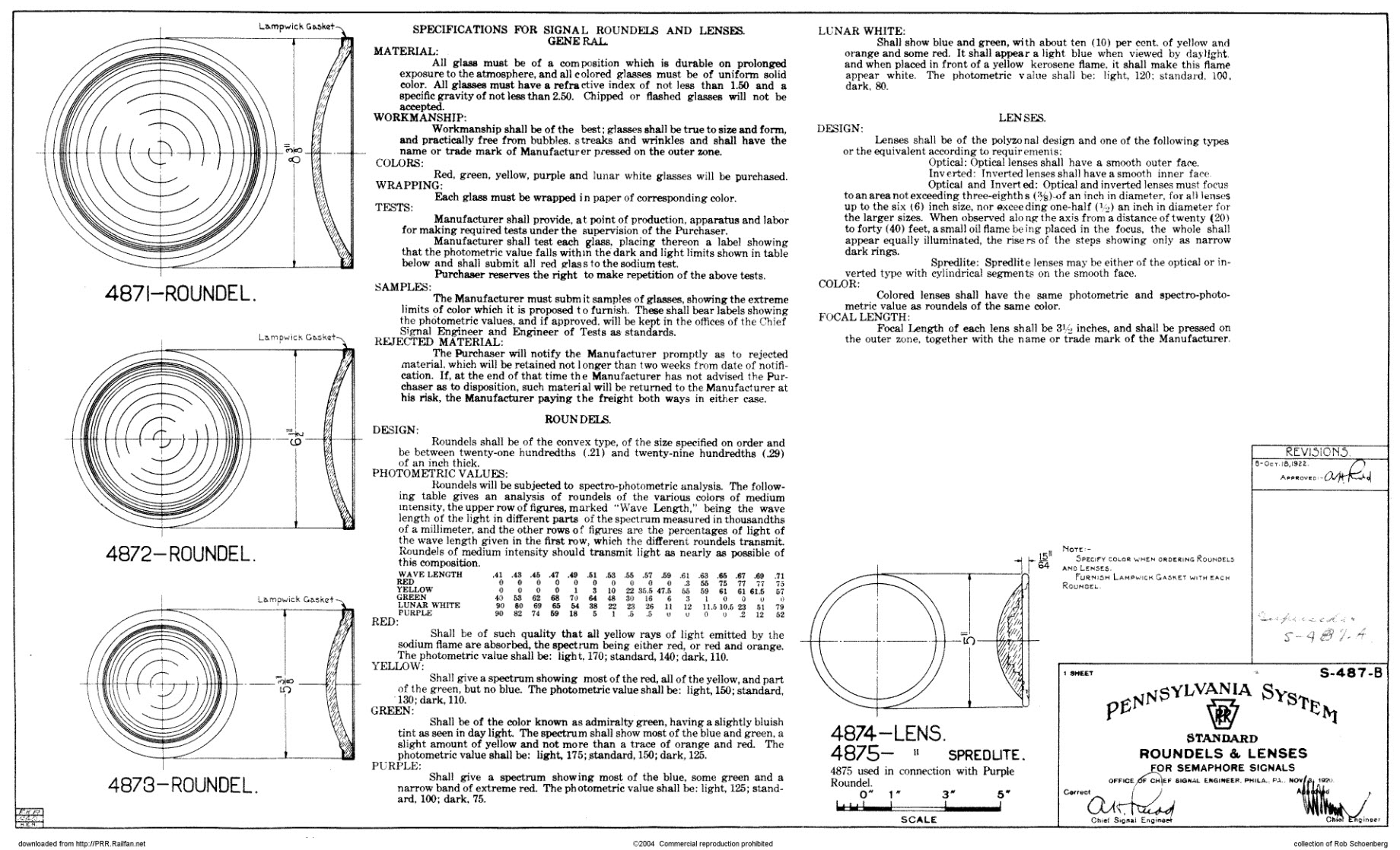
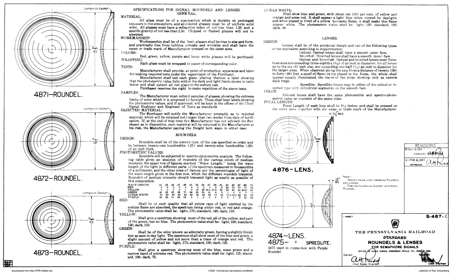
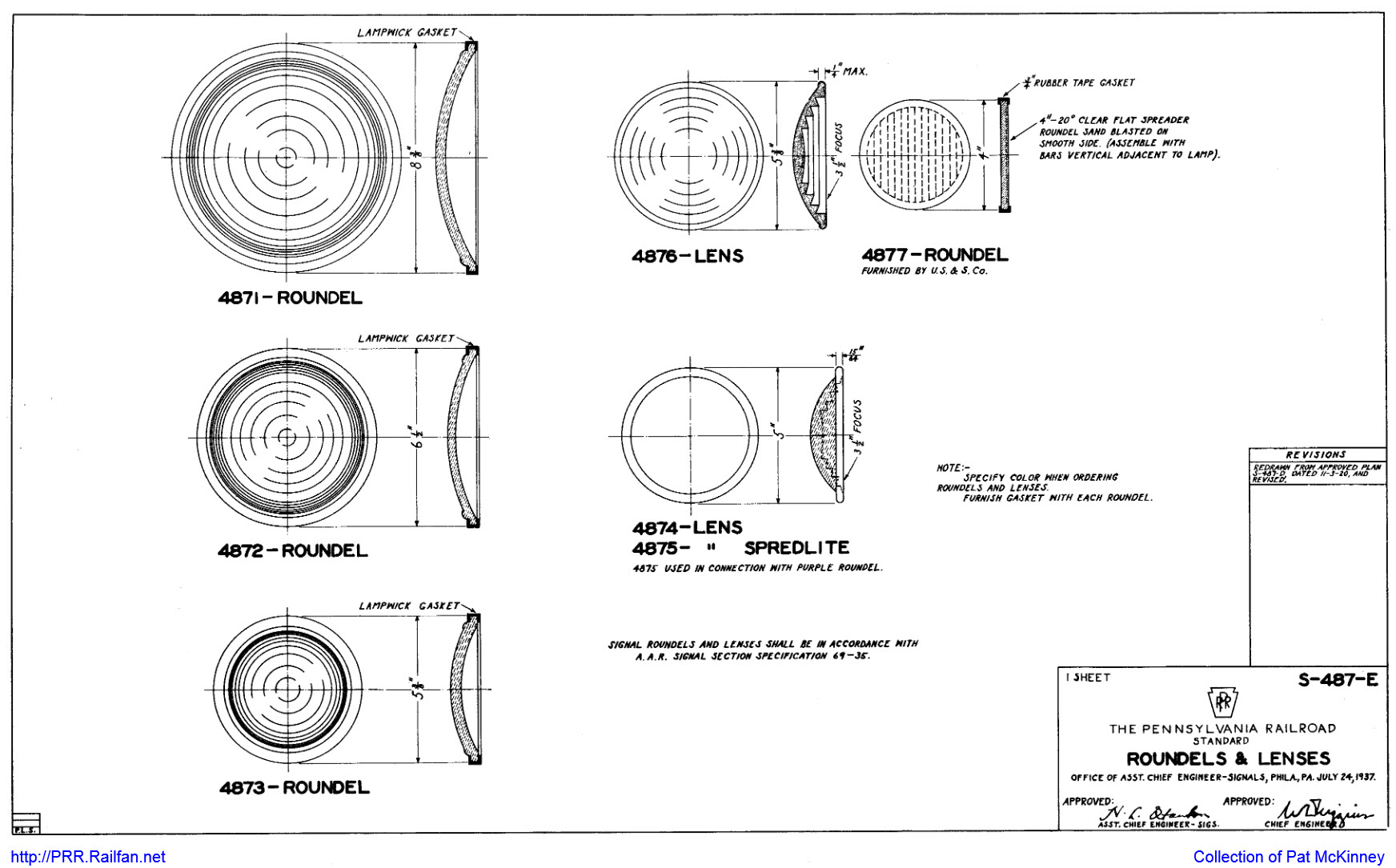
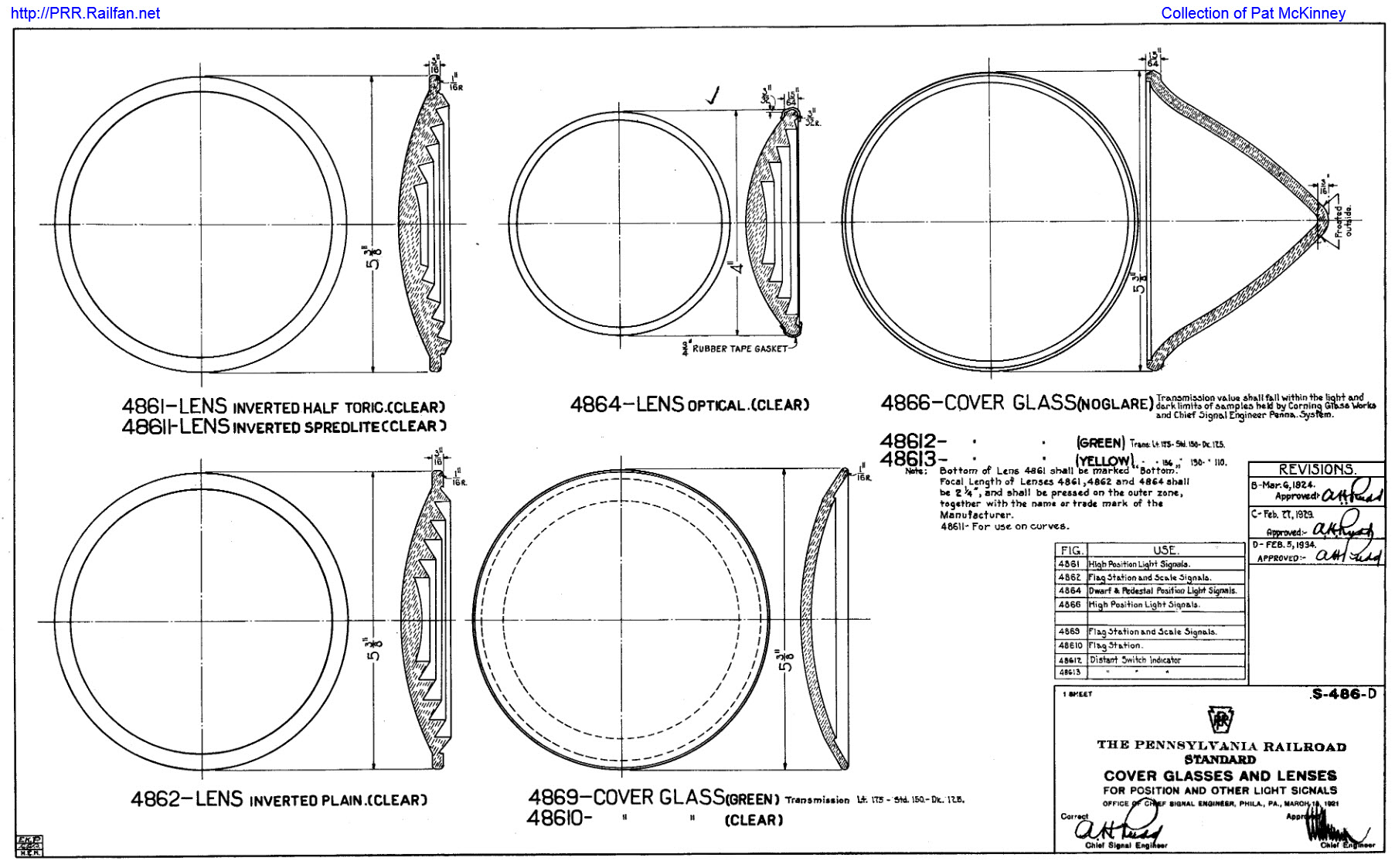
Picture 30, 31, 32, and 33
Various Pennsy roundel and lens drawings
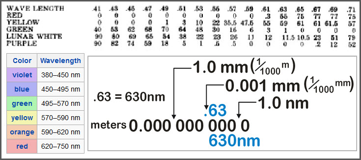
Picture 34
FYI - Relationship between nm and the PRR wavelengths numbers
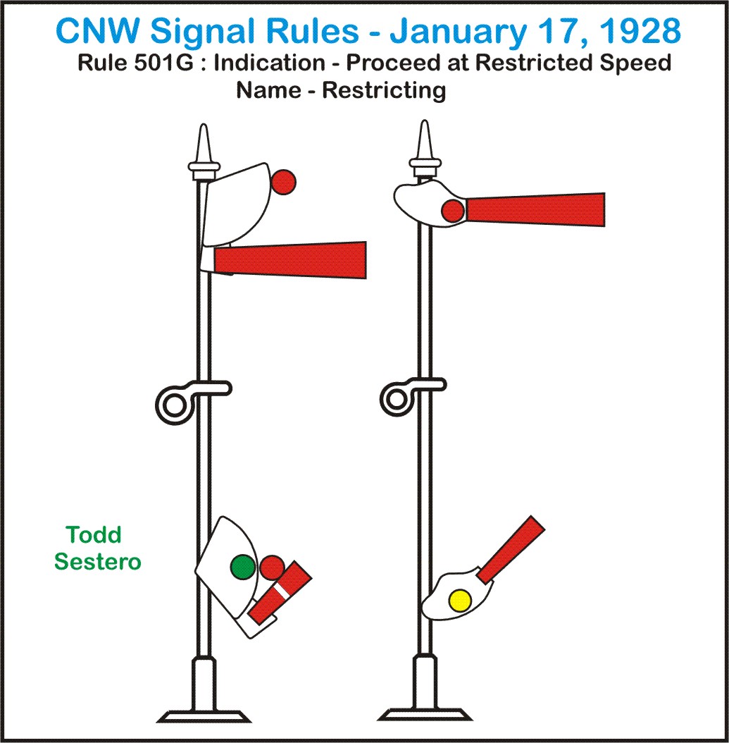
Also used on many roads were qualifier
lamps used “down” the mast from the semaphore. These could be stationary
“markers”, another semaphore, or a dwarf semaphore. The marker lamps could
consist of a single lamp, or two lamps in an assembly… green and red were often
used together to give the engineer a yellow appearance from a distance. (again,
see the CNW aspects) As an interesting note, I can remember when traffic lights
did the same thing in New York City (late 50’s, early 60’s), where the lights
had only a green and red lens, and they would illuminate both of them before the
light turned to -red-!
Picture 35 and 36
Modifications to a semaphore signals aspect thru the use of auxiliary signals,
but giving the same indication.
7h) Oh Yea, What’s With The Shape Of The Blade?
The shape of the semaphore blade does impart information
to the engineer of a train.
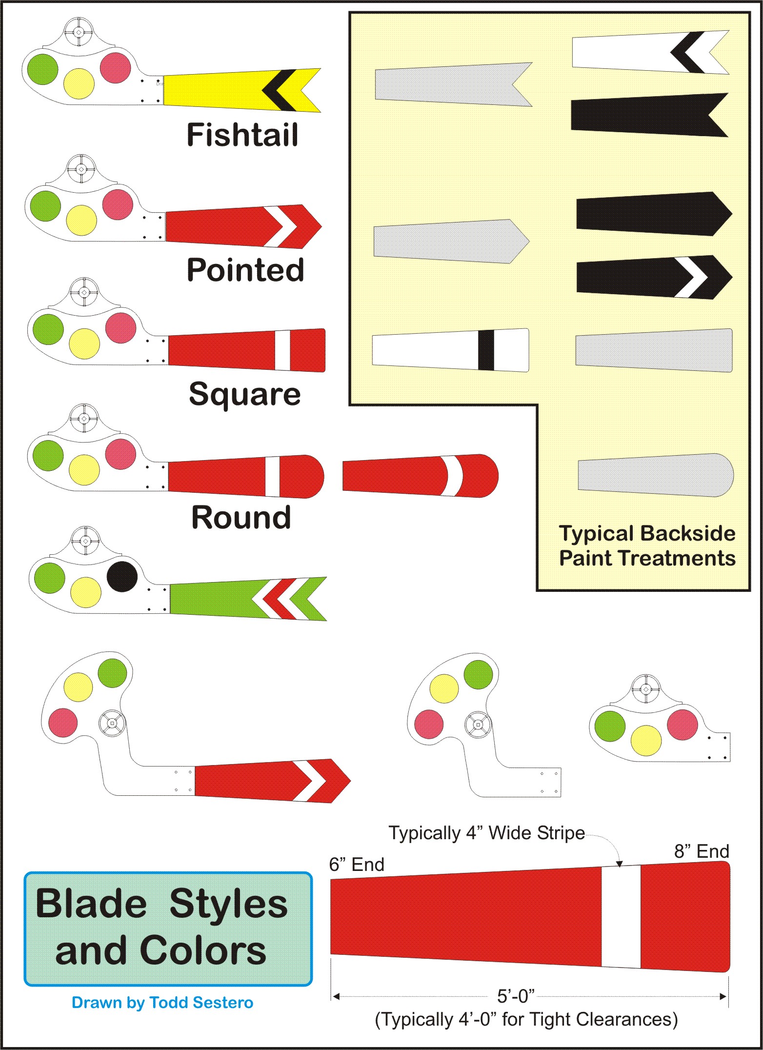
Blade ends generally came in four shapes:
1) Square,
2) Rounded,
3) Pointed (pointed "out"), or,
4) Fishtail (pointed "in").
Square end blades were commonly used as an
absolute signal, such as a block or interlocking home signal.
The pointed end blade was most often used with automatic home block signals, and sometimes as a train order signal.
To forewarn an engineer of an upcoming signal,
distant signals were employed,
and they usually employed a fishtail shaped blade.
Round-ended blades were most often used as train
order signals, but also as block signals or interlocking signals
under special rules.
Picture 37
Variation in Blade Styles and Colors.
Picture 38
Rounded type semaphore blade.
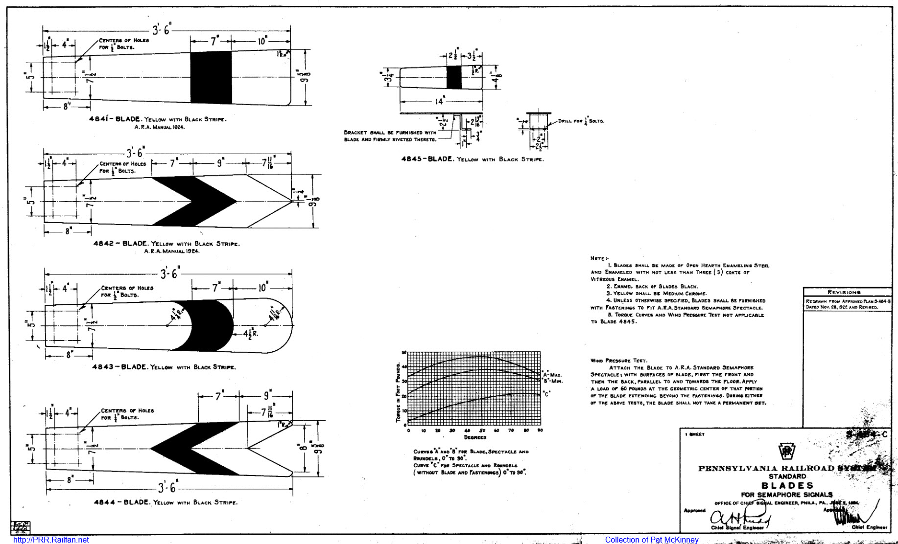
7i) Semaphore Blade Sizes
The size of the semaphore blade was
related to it’s function and application. Obviously, a standard four or five
foot long blade could not be used in the yard on a dwarf signal, and not just
because it was physically too large. A dwarf semaphore did not need to be seen
from the distances that a dwarf signal does… the train just isn’t moving as fast.
7j) Blade Color
The color of the semaphore blade also played an important part in the correct
interpretation of the signal. The great majority of blades were painted red on
their “front” surface, with a narrow white stripe, almost universally following
the shape of the end of the blade. Almost all square, round, and pointed end
blades were painted so.
Distant signals were less universally
colored, but yellow with a black stripe was a common practice. The CNW painted
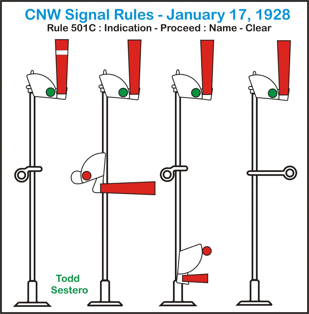
their distant signal blades a bright green color, with a red stripe.
Picture 39
CNW distant signals.
On the back side of the blades, which faced
away from the direction of movement, or the direction from which the engineer
would view a signal, colors commonly used were black and grey, some with white
stripes, and some with none – usually the grey ones.
The simple answer is: The actuating mechanism......
The first such signals were purely mechanical - locally using some sort of
a lever to actuate, or move the semaphore blade via cables, wires, and/or pipes
from a "remote location" such as a tower. Between the
semaphore and the actuating lever, there was a system of connecting rods,
cables, wires, rollers, bearings, and supports. If
the lever was at the base of the signal mast, it reasons that the linkage was a
simple affair. If the signal was remote to the tower location, there could be
(many) hundreds of feet of connecting rod between the two locations, which made it
difficult for the tower operator to actuate the signal - even more so in
inclement conditions such as snow and ice.
In a tower setting, they eventually settled on a system of interlocked levers
which needed to be pulled towards the operator to change both switch/turnout positions
and signal indications.
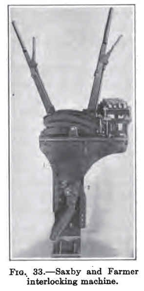
Picture 40, 41, and 42
A single lever section from a Saxby & Farmer interlocking machine, and
a typical connection for the wires controlling the blade.
8a) Mechanical Types
Power actuated semaphores finally came to
the rescue, first with a mechanical/pneumatic mechanism. Electrically operated
systems eventually came to be, and made the process of moving the semaphore
blade a much easier task, only requiring the levers to actuate a set of
contacts. The first such electrically operated semaphores were a combination of
pneumatics and electricity, where the electric energized a coil, operating a
pneumatic valve, which in turn supplied air to a pneumatic cylinder which
actually moved the blade and spectacle.
Eventually, a reliable motor was developed, and semaphores were operated strictly on electrical power.
Picture 43 and 44
Two mechanical dwarf semaphores, notice the one on the left is unlit!
8b) Pneumatic Types
The first power type semaphore signals were operated on air, and we refer to
them as pneumatically operated. 8c) Electro-Pneumatic Types
This type of actuator combined the advantages and simplicity of electrical
control, with the inherent power of air. Picture 45
US&S top-of-mast pneumatic actuators.
8d) Electrical Types
Once suitable motors were developed, they were put into widespread use, and
almost every semaphore used them except where they might have kept an older
model employed. Motors came in both AC and DC models, and came in voltages
ranging from about 8VDC, to about 120VAC.
In upper quadrant semaphores, the motor
lifted the blade to the approach and clear positions, gravity would bring it
back down, softening the drop with a cushioning device. Once in the approach or
clear position, a small pawl would engage the shaft and hold it in place. This
pawl was connected to a solenoid, or holding coil, which was always powered in
the approach and clear positions. If the solenoid lost power, either
intentionally or not (in the event of a power failure), the pawl would disengage
the shaft. In a power outage, this allowed the blade to come down to the stop
position. If intentional, the blade would be going from the approach to the
clear position. The holding coil needed very little current to operate, and did
not substantially affect the power draw in the days when semaphores were
operated by batteries, away from a power source.
The motor itself was connected to the
semaphore shaft, usually via a set of gears. This allowed the use of a smaller
horsepower motor, to operate a heavier load. There was a fair bit of over
design, as semaphores in the north had to contend with snow and ice, which could
make the blade very heavy, if not frozen completely into place. One of the
spectacle’s purpose was to provide sufficient counterbalance for the weight of
the blade, thereby easing the power requirement for the motor.
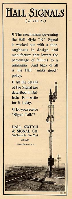
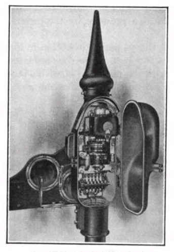
Picture 46
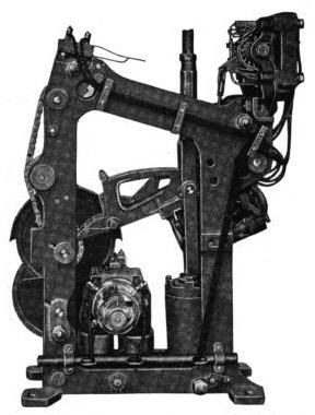
An early Hall top-of-mast electrical actuator – Style K.
Picture 47
Cross sections of a Federal motor.
Picture 48 and 49
Two cross sections of a later model Hall motor.
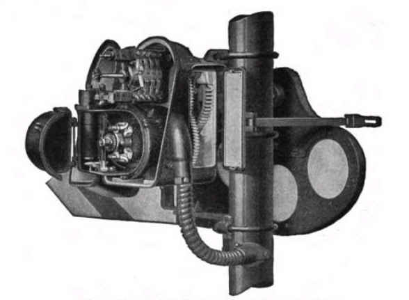
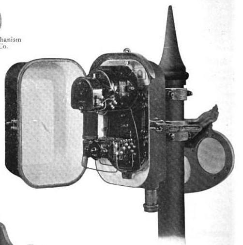
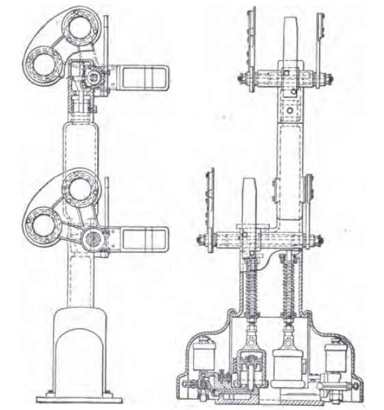
8e - Location of the Actuators
The actuator, whether it be an electrical motor or a pneumatic device, could be
located at either the top of the mast, behind the spectacle, or at the bottom,
or base of the semaphore.
In a multiple arm signal, and the actuators were located at the base,
there was generally a separate case for each actuator.
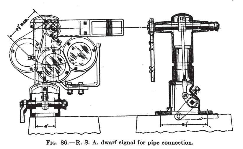
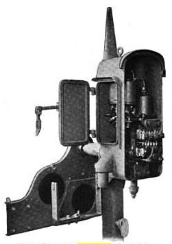
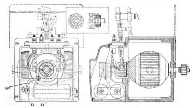
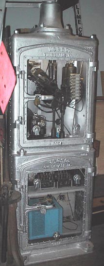
Picture 50
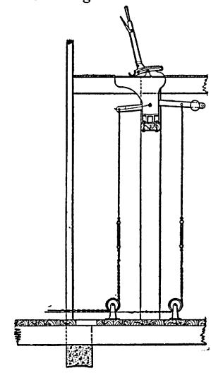
US&S base-of-mast installation where the mechanism is in the upper
case, and the relays and power supply are in the lower case.
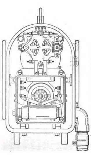
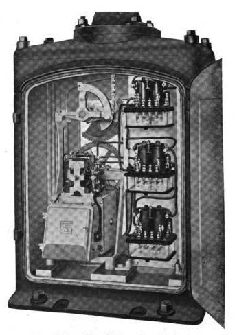
Pictures 51 and 52
Federal base-of-mast and top-of-mast electrical actuators.
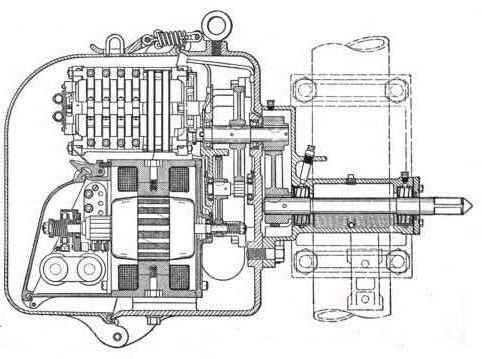
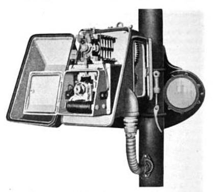
Picture 53 and 54
GRS base-of-mast and top-of-mast electrical actuators.
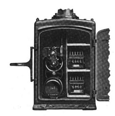
Picture 55 and 56
US&S base-of-mast and top-of-mast electrical actuators.
Unlike with other signal types, where one commonly refers to a signal as a two or three head color
light signal, a semaphore was a semaphore, regardless of how many were used on a
single mast, be it one, two, or three – each one was treated as a separate
signal. It just so happens that the indication required the use of one, two, or
three semaphore signals.
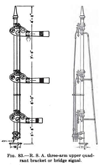
Picture 57
A three semaphore mast, probably for mounting on a standard signal bridge due
to the fact that the base is only 3ft below the first semaphore.
Picture 58
A two semaphore dwarf installation using rods to position the blades.
Semaphore signals were fairly unique in yet another instance, whereby system designers would often
place both a several signals on the same mast. This is one of the reasons
different shapes and colors were used for the semaphore blades. Picture 18
and Figure 20 show this. In Picture 18, the mast contains two signals
indicating two different things to the engineer. The top signal gives an
indication for the block immediately ahead, and the lower (distant) signal,
gives an indication for the block beyond. On the left, both blocks are
clear. On the right, the 2nd block is occupied, and the engineer needs to
take action to slow the train. Figure 20 shows an application where space
was (probably) limited, and they put a dwarf signal on the same mast as a high
signal. The B&O is one railroad that continued the tradition, by placing a
dwarf signal at the bottom of a mast for a high signal, at the end of a siding -
when they did this tho, they also used a doll arm to tell the engineer the high
signal was for the left track.
Picture 59
Mast with both intermediate and distant semaphores.
Picture 60
A high signal and a dwarf on the same mast, to save space and from
putting in another foundation - notice the dwarf uses a shorter blade.
In the old days before we had all sorts of techno gizmos like GPS and radio
communications, there arose the need to not only control trains, but to place a
physical barrier in the path of an oncoming train. For this purpose, an
elongated blade was developed, which the end of would stand in the engines
path. These were typically used in cases where there was an immediate threat of
danger, such as an open bridge span, or any other readily identifiable source of danger.
Picture 61
A typical mechanical smashboard installation.
Picture 62
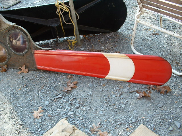
Restored smashboard blade by ADB,
it is seven (7) feet long, and was painfully restored with over a quart of wood
filler, and has the exact "Chrome Yellow" paint on it that the standard Pennsy
plans call out for. This blade is supposedly from the Bridgeport NJ
drawbridge.
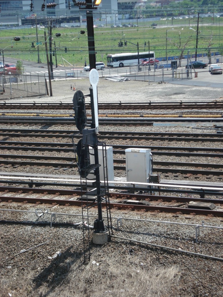
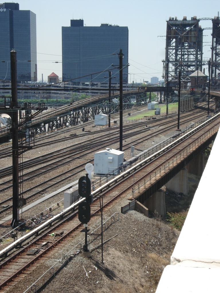
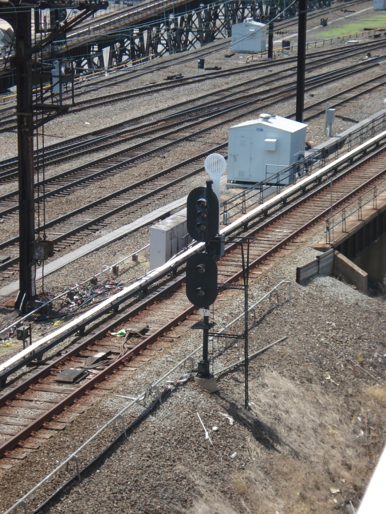
Pictures 63, 64, 65, and 66
This set of four pictures was sent to me by Rich W up Newark NJ way, and
they are of a smashboard installation on the WB PATH track heading towards the
DOCK bridge on its way into the Newark station. Many thanks to Rich for
taking the time to go and take these pictures for me and you! I came
through here around 9pm on National Train Day 2012, so I could not see them :-(
Maryland and Baltimore's last semaphore was on the CSX, enroute from
Baltimore to Gray's Yard (in Sparrows Point).
It permanently displayed a restricting aspect. The signal was taken down in 2006 by CSX.
Baltimore MD
Mechanical semaphores protecting a B&O / PRR Diamond.
These signals protected a long gone diamond between the PRR and the B&O in
the Canton area of Baltimore MD, leftover from the days when the B&O used a car float
to get passenger trains into downtown Baltimore, way before they had their
northern route into Camden Station via Mt Royal and the Howard St Tunnel.
The diamond and semaphores were removed sometime in the 1970's - I guess I was
lucky to catch what was left! The clear board in the left photo is for the
Pennsy, and the stop signal on the right is an indication for the B&O coming out of the docks.
(For more info click here)
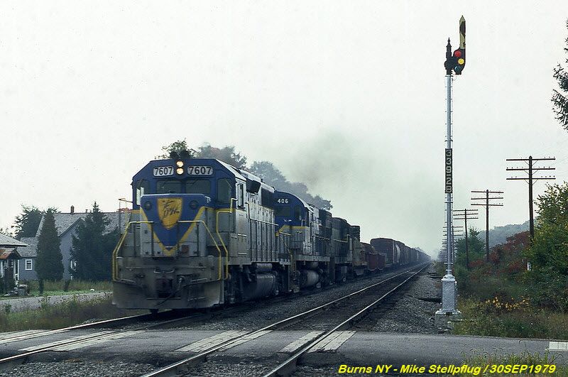
Burns NY - On the D&H
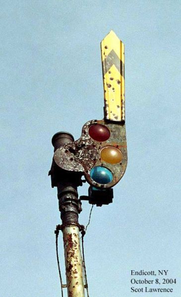
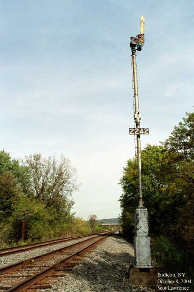
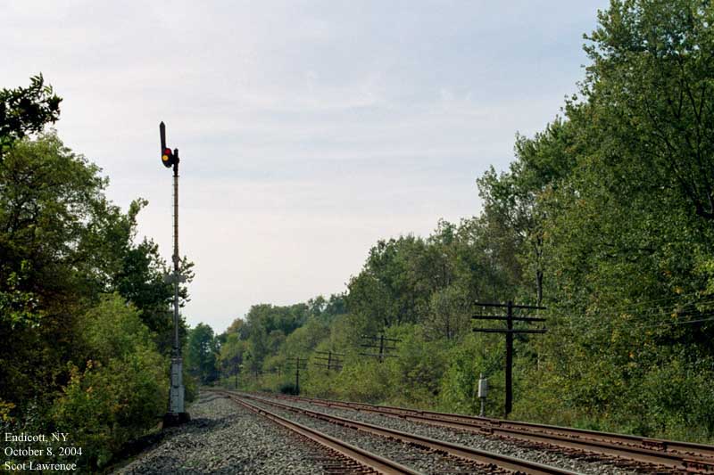
Endicott NY - The last Semaphore on the Southern Tier