Please note: Many people read my website, and I don’t have a clue as to what level of expertise the reader has under his or her belt, so to speak. So with that in mind, I am going to assume that you know absolutely nothing about relays and/or electricity. For those that do, please bear with me. Thanks.
NOTE: If you are ever in search of a relay to buy, and decide to check out EBay, remember that most of these relays are quite heavy, so there will be a hefty shipping fee on top of the purchase price! Some sellers are quite reasonable in their listing price, others can be quite outrageous, as seen below.
Acknowledgements: I would like to thank Bob Braden for his help with this section.
As always, if you have something to add or correct, please check hereLet's go over a little signal history before we dig into relays. When railroads came around in the 1830’s, trains only operated during the day, and there weren’t many of them. So in the beginning, railroads did not need signals. Yet, even with daytime operation only, the railroads saw a need to protect people from the trains where ever the tracks crossed a road. So the first form of signaling were signalmen placed at the crossings to stop traffic from crossing the tracks when a train was approaching. My signal timeline page outlines the significant events in railroad signaling, and is here. Eventually, railroads wanted to run at night, they wanted to run more trains on the same track, and they wanted to run opposing trains on the same piece of track. So the railroads were now in a quandary as to how to effectively manage the trains without them running in to each other. In the early days, all sorts of mechanical and man powered schemes were used to regulate trains. Some were more effective than others, and the ones that didn’t do what they promised, fell into the history books rather quickly. If you have the patience, the U.S. Patent Office’s data base will show you some very interesting railroad devices. Eventually, the basic electrical track circuit was developed by Dr. William Robinson in 1872, and from there, a whole host of semi-automatic and fully automatic signals were developed. Then, once a suitable incandescent light bulb was developed, reliable night time signals could now be made (and seen). But none of it would be possible if it were not for the development of the relay. I will say “development”, as opposed to “the invention of”, because the basics of the relay existed in the form of the telegraph, and may have existed in other devices prior to that, so there was a progression in adaptation and technology which gave birth to the railroad relay that were are familiar with today.
Relays: without relays, modern railroad signaling would not be where it is today. The relay forms part of a simple (basically) three element circuit, consisting of the relay, a battery, and the track. This simple circuit forms the basis of a signal system, and is called a track circuit. A track circuit is responsible for detecting the presence of a train, engine, car, or anything else in its protection zone, usually called a block. A track circuit by itself, in all but the most basic signal systems, only forms half of the complete signal system. In order for the signal system to display more than just green or red, additional relays will be needed to perform some sort of simple logic. These extra relays will allow the signal system to display the advanced aspects needed in modern operation, and include things like interlockings, grade crossings, sidings, crossings with other rail lines or tracks, bridges, etc into the decision making capability of the relay logic.
Today’s modern signaling systems have progressed beyond using track circuit relays in the traditional sense, being replaced by electronics, but there are still many, many railroads out there whose signaling systems rely on the use of relays. This page, however, will concentrate on the electro-mechanical relay, or, just plain old relay.
A relay is an electrical device, that upon the application of an electrical current, becomes magnetized and pulls in a set of contacts. A relay is used to control, isolate, and/or activate another electrical circuit.
Let's build a relay piece by piece. The first building block of a relay is the core. Relays use a magnetic field originating from the core to attract movable pieces. The core is made of iron..... stainless steel and aluminum will not work because they can not be magnetized.
The magnetic field is generated by applying an electrical current to a coil. The coil is wound around the core, usually on something that insulates the coil from the core, sometimes called a bobbin. This assembly is also known as an electromagnet, or a solenoid (if the core is hollow). In contrast to a permanent magnet, like a bar magnet, the things you stick on the door of your refrigerator, or the one in your speakers which create a magnetic field all the time, an electromagnet's magnetic field is controllable.
You can make a simple electromagnet by taking a nail and winding wire around it (if you want to try this, use a larger nail, like a 10 or 12 penny nail, and wind about 200 turns of #22 AWG magnet wire around it, then tape it down with electrical tape). If you take a battery, like a 6 volt lantern battery, and connect it to the wires of the coil, the electricity flowing through the coil creates a magnetic field. If you have electric locks in your car, they are activated by solenoids. Another common place you will find a solenoid is in your starter motor - a solenoid pulls a small gear out to engage the starter motor to the flywheel of your engine... OK, enough on these guys.
The next step in building or relay, is to mount the coil assembly to a frame, and then add something that moves, for without something that moves, we can never have a relay. We will use another piece of steel or iron for the coil to attract, we'll call this piece an armature. So far, we have what they call in telegraphy, a sounder, a device, that when energized, will make a click that can be heard. This is why I said above that relays were developed, and not really invented.
Finally, to the armature, we will connect in one fashion or another, a set (or sets) of contacts. NOW we have a relay. The contacts can be arranged so they will either open or close when the relay is energized. As stated already, the relay gives us a way to electrically control another circuit, and this is fundamental to the understanding of how systems built around relays work.
If I can digress for a minute back to the starter motor, there's a thing hanging off the side of it called a solenoid, but it also doubles as a relay, controlling the battery voltage to the starter motor in addition to pulling out that pinion gear. BTW - In some cars, mostly older ones, the relay is separate from the starter motor and solenoid. A nicely illustrated primer on relays used in cars is at: http://www.bcae1.com/relays.htm.
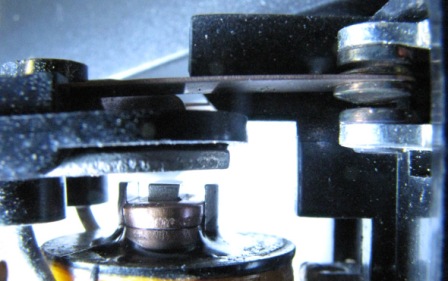
Picture 1 shows a simple (non-railroad type) relay in its un-energized position. Picture 2 shows it in the energized position, notice how the armature has been pulled down to the core of the relay, and that the contacts on the right side of the photo, are in the up position in the left photo, and the down position in the right photo.
Picture 1
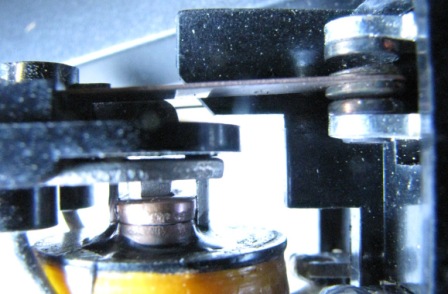 Picture 2
For every “field”, there are oodles of specialized relays
developed to meet a specific need. For instance, in the field of
telecommunications, the following pictures show a few relays from the
telephone industry.
Picture 3a
is a
line finder relay.
This relay looks for a ground on an incoming subscriber circuit when you
pick up the phone. Once found, it will place a dial tone on the
line and wait for the dial pulses, which will get passed on to
additional Strowger relays.
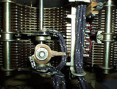
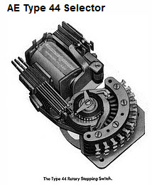
Picture 3B
is a
Strowger (or "step by step") switch
for a rotary telephone system, one that could increment one “notch” for
each pulse coming from the old rotary telephone dials. This relay
performed in two axis': up, and then around, so it could accommodate two
of the three, four, five, or seven numbers of a telephone number (yes,
going back to a three digit phone number goes back a long, long ways!).
Strowger switches were used as early as the 1920's.
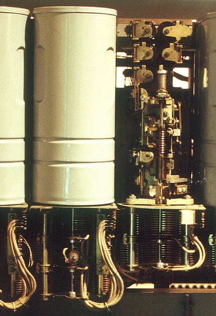
Picture
4
shows a relay that could be used in a pinball machine (it's
another telephone relay tho), and would
typically count the number of times the pinball hit a particular bumper,
and then control the appropriate lights on the playing board, or maybe a
score counter, and/or provide a feed to another relay. I mention these
relays only to illustrate the difference between them and railroad
relays when I get to that point in this discussion.
We will talk more about
contacts later.
More info on telephone type switching systems can be found
here.
![]()
 Picture 3a
 Picture 3b
 Picture
4
Picture
4
Relays come in many varieties, the most simple of which are DC and AC versions. DC relays run off of the voltage that comes out of a battery, which only flows in one direction, and the DC stands for Direct Current. AC relays will operate on Alternating Current, which is what you have coming out of the wall in your standard 120VAC receptacle.
Most relays are designed to operate off of a low voltage, like 12VDC, and some, like track relays, are designed to operate from far less, typically the voltage coming out of one cell, which is normally one and a half volts. More on why track relays operate on such low voltage later. Some relays designed to work with railroads powered by overhead lines, such as the New Haven and Pennsylvania Railroads, operated off of 110VAC.
Other terms you will hear in connection with relays is Neutral, Polar, and Latching.
A Neutral Relay is one that is either energized or not. When energized, it pulls in, or picks the relay. When un-energized, it releases and the contacts return to their un-energized state. Relay contacts are usually shown on schematics in the un-energized state unless otherwise stated.
On the other hand, a Polar Relay has three states. It can be un-energized, it can be energized by a polarity in one direction, or it can be energized by a current of the opposite direction. Equate it to taking the battery and flipping it around so the current flows in the opposite direction. We will see later on how a relay like this can save the railroads a considerable sum of money when running wires over long distances, because we only need two wires instead of three to get a control signal from one place to another. Polar relays can also operate on AC, believe it or not. This is accomplished by connecting the main coil to the power source so it is always hooked up the same way, every time the relay is energized. Then, on the armature, they place a second coil of which they can change the the way the coil is connected to the power source, effectively changing the "polarity" of the AC current energizing it - this will make it rotate one way or the other.
A Latching Relay is one where the relay has two positions, but power is only needed to get it into the other state, but NOT needed to maintain it in that position. You can see where this would save electricity, and therefore, money for the railroads. There are latching relays that use two coils to move the armature into position, one coil for moving the armature in each direction (and then it is held in place mechanically), and there are relays that use one coil where the designers cleverly designed the mechanism to take advantage of the residual magnetism to keep the armature in place.
Several other terms I should touch on here are Heel and Back and Front Contacts, since these terms are frequently used when talking about railroad relays. A Back Contact is a normally closed set of contacts, or those which have continuity with the armature when the relay is unenergized. A Front Contact is a normally open set of contacts, or those which have continuity when the relay is energized. The movable part, or armature, is referred to as the Heel.
A complete list of relay related terms is located at the bottom of the page.
In its most simple form, a track circuit consist of a relay and a battery, interconnected by wires and the track. In normal operation, without a train in the block, the battery energizes the relay via the current flowing through the rails. This is shown in Figure 1.
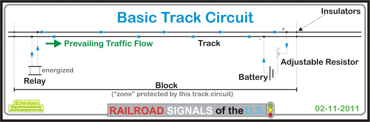
Figure 1
If a train enters the block, what happens? The wheels of the train shorts out, or shunts the current going to the relay, and the relay is no longer energized. Figure 2 shows us the current flow when a set of wheels has entered the block.
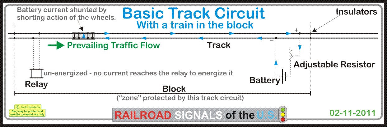
Figure 2
If we start off with a very simple two color signal that displays only red and green, when the relay is energized, the relay will make the signal display a green. When the trains appears in the block, and the relay becomes un-energized, the signal “turns” to red.
So why didn’t signal designers just make the relay energize the red as the train entered the block, then we wouldn’t have to power the relay all the time a train is not present (thereby shortening battery life, which was important in the early days of signaling when there was NO local source of AC power to keep the batteries charged)? This is done to give us what we call a failsafe circuit.
Failsafe means that if something in the circuit "goes wrong", it fails to the safest mode it was designed for. In the case of railroad signaling, the safest aspect that can be displayed for a train is STOP. This way, the train won’t advance and risk the possibility of running into another train or some other unsafe problem/situation. After all, that’s the biggest reason why signal system came about, to make travelling by trains safe.
We make the circuit failsafe for a number of reasons, such as (but not limited to): 1) if the battery is too weak to power the relay, the signal will always display red (as long as the power source for the signals is also good). 2) If a wire breaks, the signal will display red, 3) If something happens to the track, like a bad bond, or the rail breaks, the signal will turn to red, 4) if something happens to the relay itself, it is also designed to fail so that the signal will turn to red.
Since this section deals with relays, we will hit on more track circuits on another page. This is just to wet your appetite! :-)
Relays were/are made by:
US&S - Union Switch and Signal, now Ansaldo. http://www.ansaldo-sts.com/AnsaldoSTS/EN/Business/Components/Relays/index.sdo
GRS - General Railroad Signal, now Alstom. http://www.alstomsignalingsolutions.com/OurProducts/WaysideProducts/Relays/
Safetran - More info can be found at: http://www.safetran.com/relays_catalog.asp
WABCO, Westinghouse Air Brake Co, now US&S
National Ziegler, previously known as National Railway Signals. I haven't been able to find out squat about this company. If anyone knows of their history, please email me.
GRS
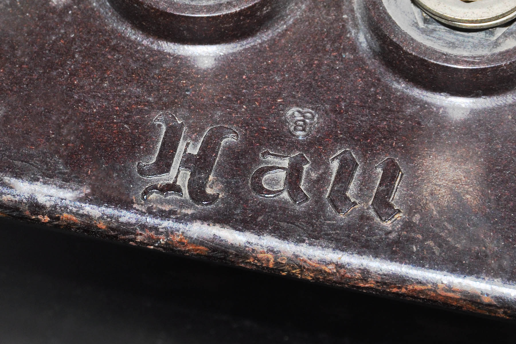
Hall
Safetran
US&S
WABCO
National
Most of the pictures featured here have been grabbed from elsewhere on the internet, mostly from Ebay listings, if you have pictures you would like to contribute, contact info is here.
In searching for information on
relays, I came across another nice collection of relay photos by Jeffrey
Seidel at:
http://railroad-signaling.com/relays/relays.html
He also has a very nice collection of railroad signals,
traffic lights, and all sorts of other interesting things!
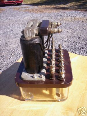
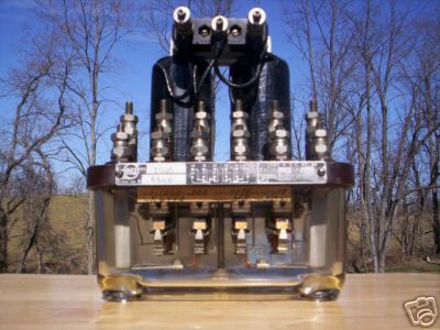
GRS Type KDC Relay
A 4PDT relay.
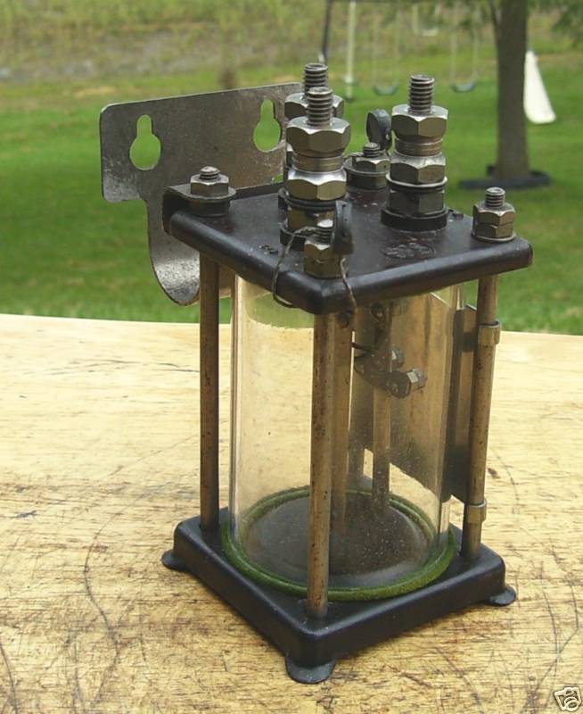
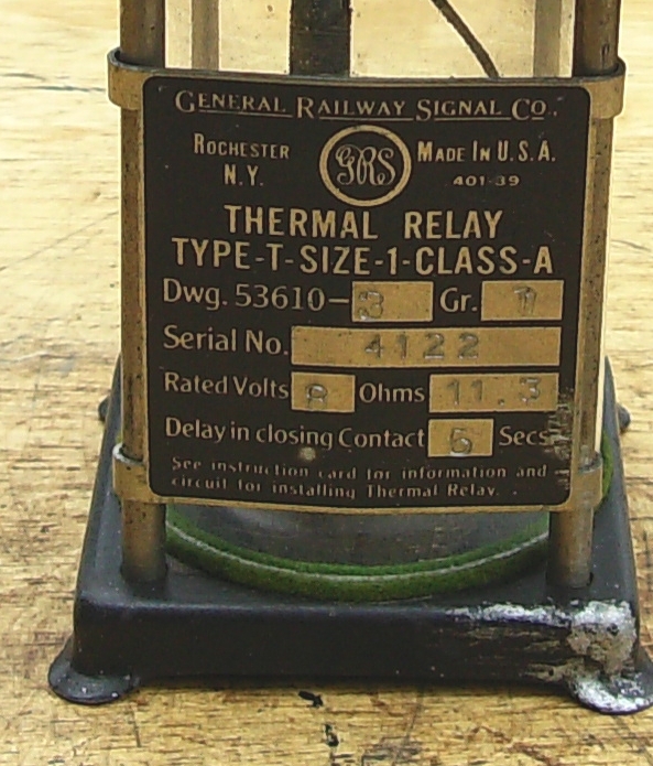
GRS Thermal Relay
Type T
This relay can also be
called a timer relay. You apply a voltage, and at some
pre-determined time later, the contact(s) open or close depending on the
relay's configuration. This particular one is designed to close
the contact in 5 seconds. The 11.3 ohm coil is rated for 8VDC.
Thermal relays operate by the interaction of two different metals called
a "bi-metal" strip. The two metals have a different coefficient of
expansion, so when a voltage is applied, the metal strip heats up, and
because of the difference, the strip actually bends. The timing is
controlled by the length of the metal strip, the metals used to make the
strip, the applied voltage, and the spacing of the contacts. This
relay was selling for 20 bucks, much more reasonable.

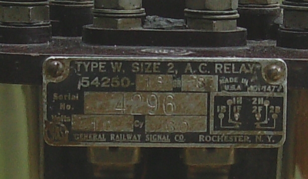
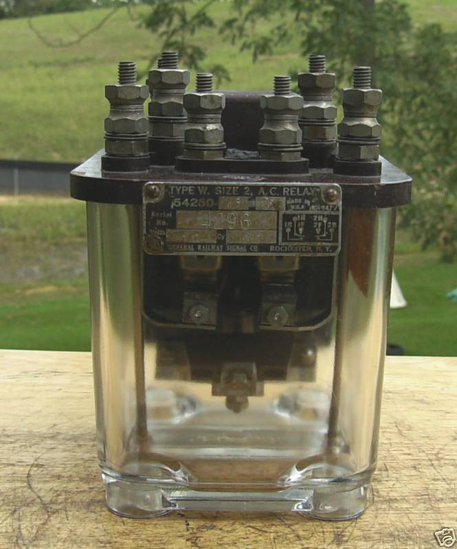
GRS Type W A.C.
Relay, Size 2
An AC operated relay
designed for 10VAC on 60 cycles. The contact arrangement is 2
poles, double-throw (DPDT). This was another relay that was listed
for a quite reasonable $20.
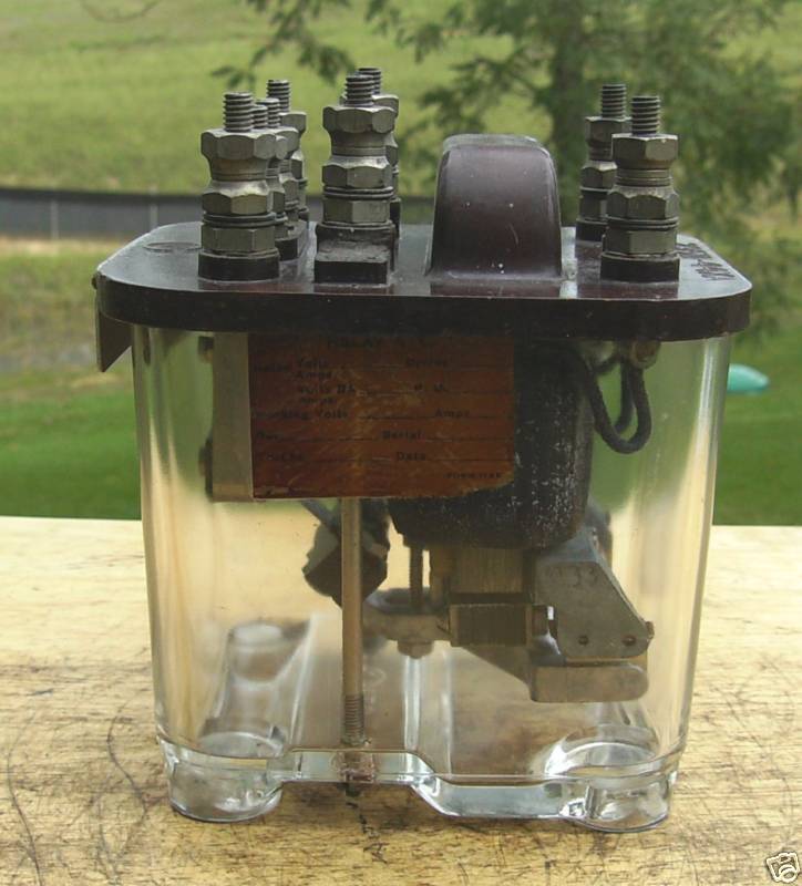
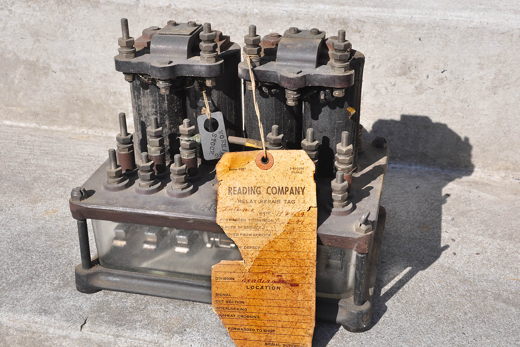
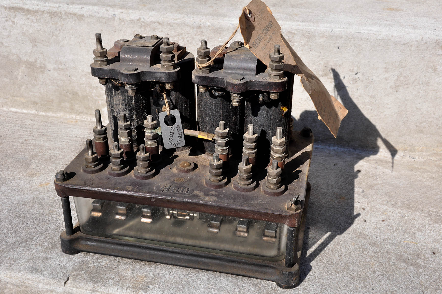
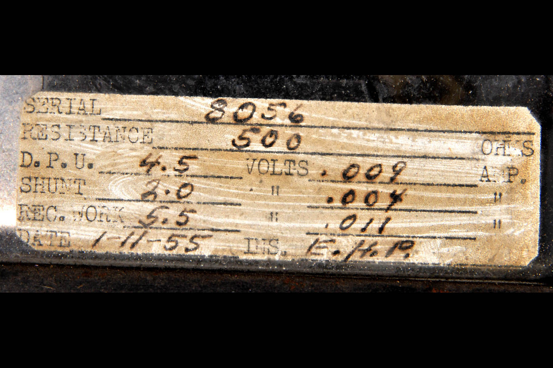
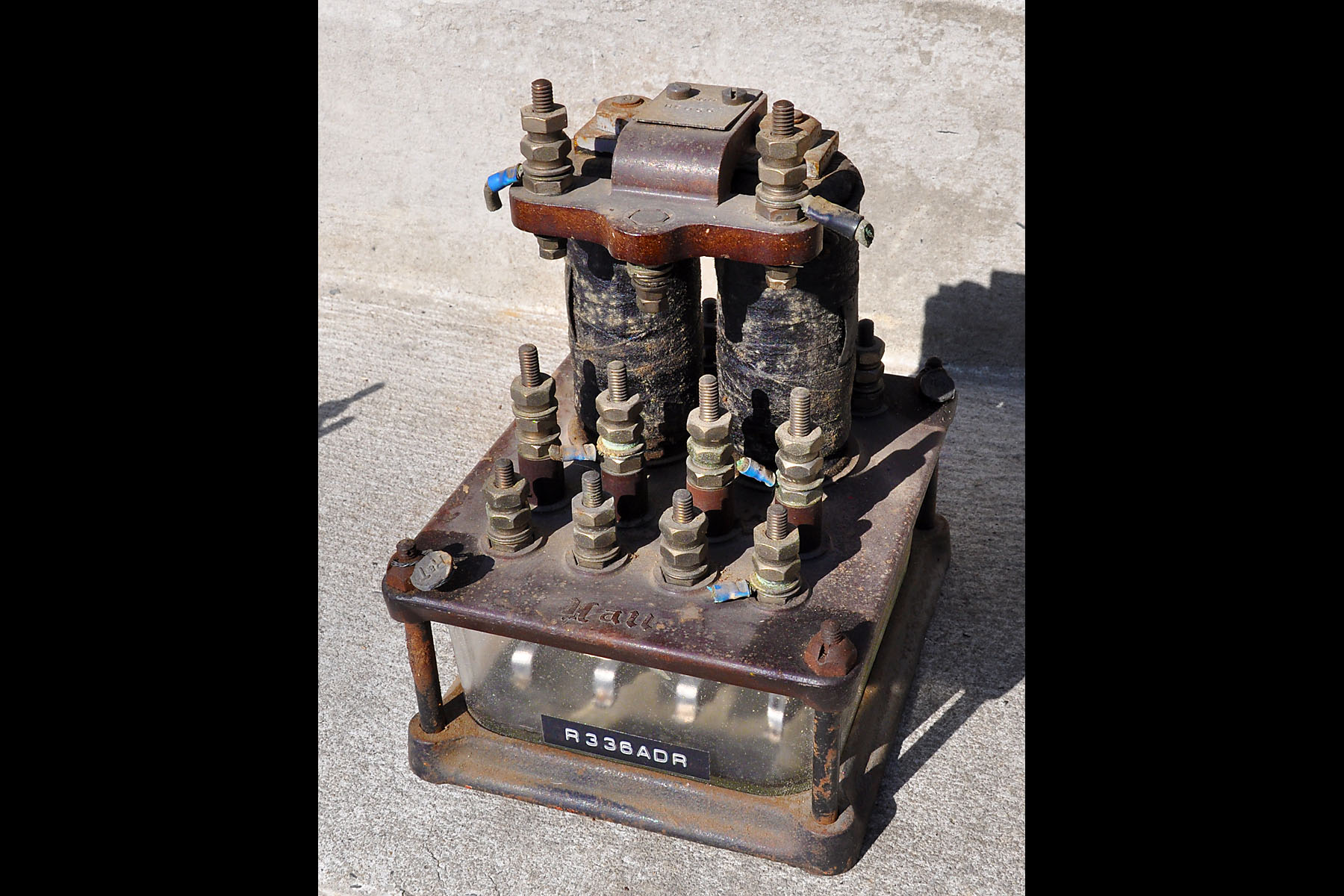
Here are a few pictures of several Hall relays sent in by a fellow signal fan.
![]()


Safetran Type ST-1 and ST-2 Relays
Safetran Models ST-1 and ST-2 are compact vitals relays, typical of the majority of relay in use today, having replaced the large bulky relays picture elsewhere in this section. These "snag" came from their website, and the specs shown below are just a small sampling of what they offer. Safetran is now part of Invensys.
![]()
![]()
![]()
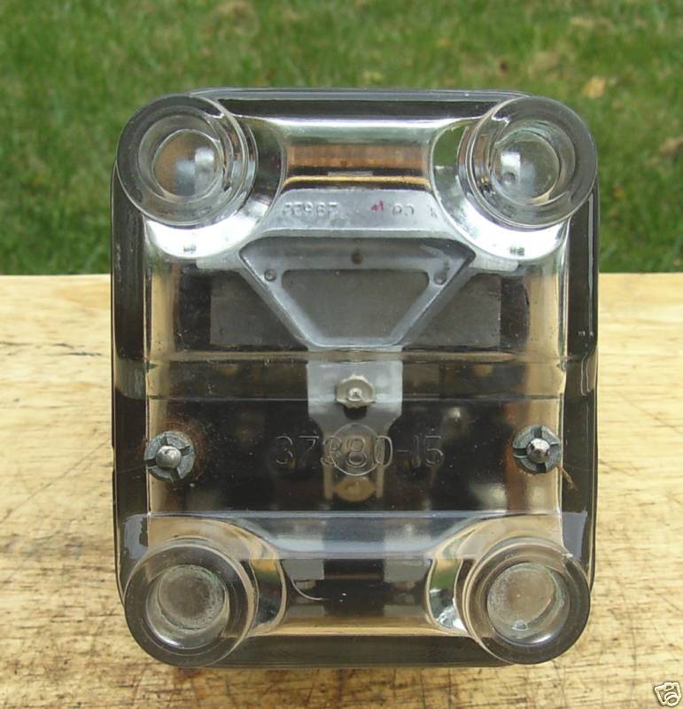
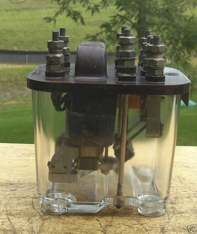
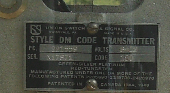
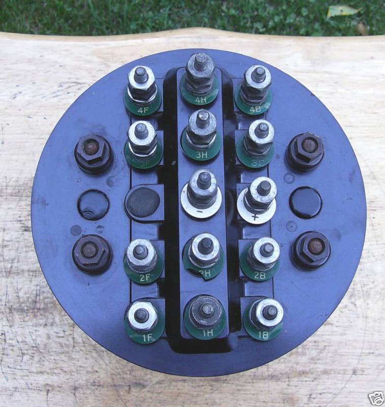
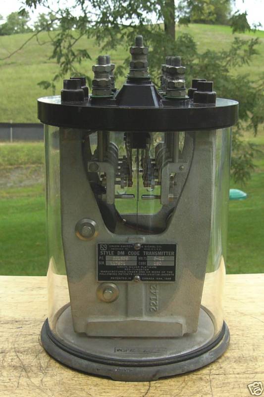
US&S DM Style Code
Transmitter
This relay was designed to
operate from 8-12VDC, and had a rate of 180 per minute. It has a
set of 4PDT contacts. From the 50's. This relay had a
starting price of 60 bucks on EBay, with a buy it now price of $225, I
didn't follow the auction to see if it sold or not. Personally, I
think the prices were high.

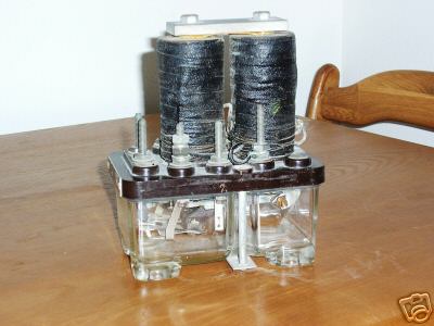
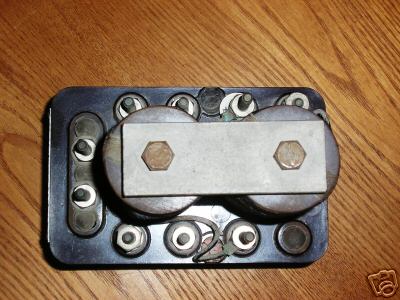
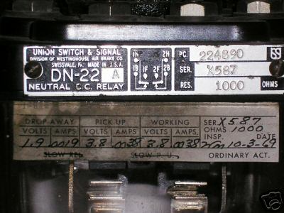
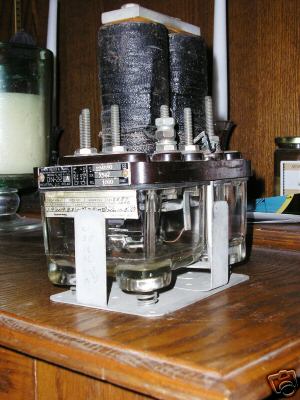
US&S DN-22
Neutral D.C. Relay
This DC relay has a coil
resistance of 1000 ohms, picks-up at 3.8 volts and drops away at 1.9
volts. It has a set of DPDT contacts. The top set of photos
is of an "A" version, the bottom set an "L" version.

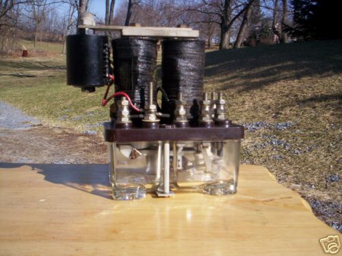
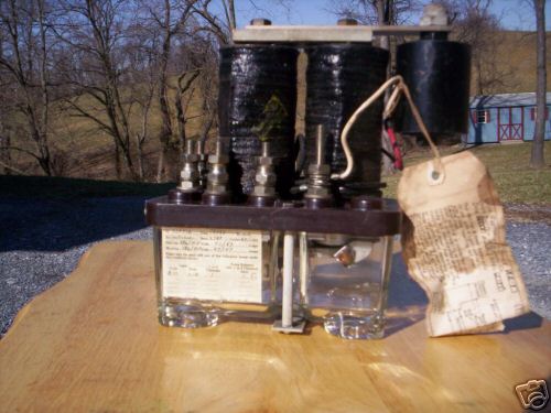
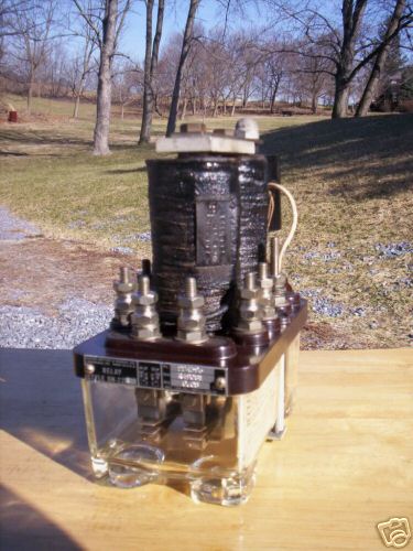
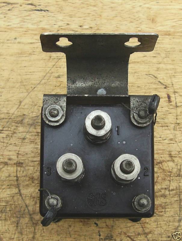
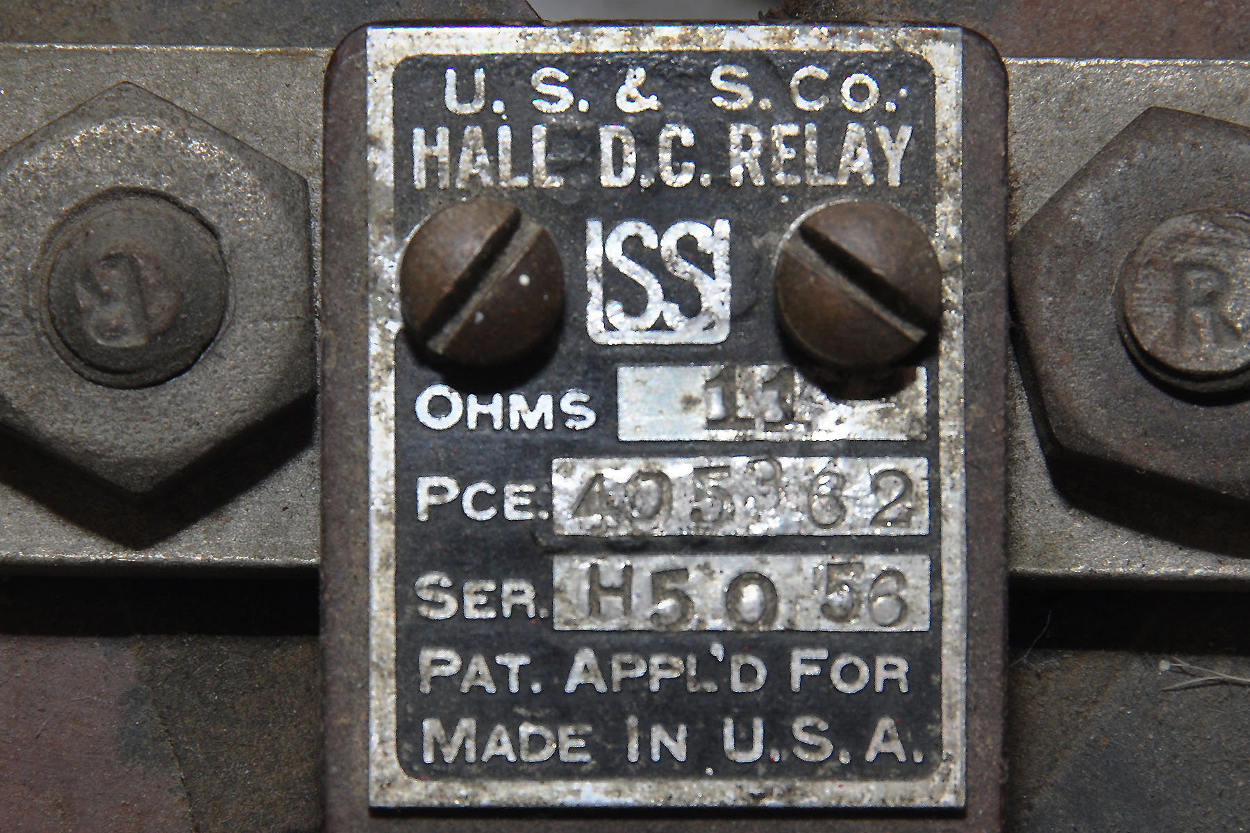
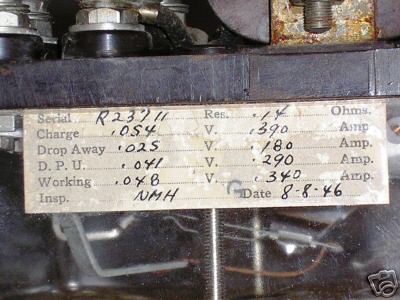
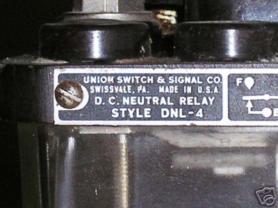
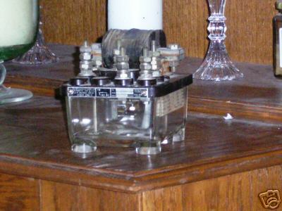
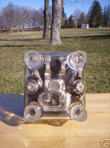
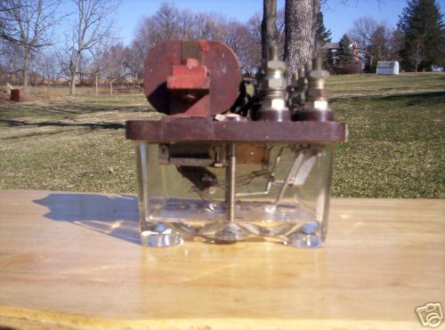
US&S DNL-4
D.C. Neutral Relay
This relay is just about as
simple as they come, with a single set of SPDT contacts. If I read
the specs correctly, it has a pickup voltage of 0.054 volts, and a
drop-out voltage of 0.025 volts. The plate says the coil
resistance is 0.14 ohms.


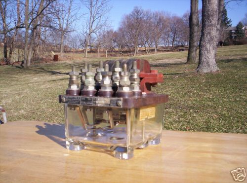
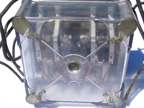
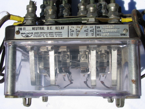
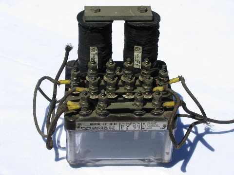
WABCO (US&S) DN-11
Neutral D.C. Relay
A typical neutral relay,
with a 4PDT configuration. According to the listing
these pictures came from, the relay has a drop-out voltage of 2.25V at
3.3mA, a pick-up voltage of 4.62V at 6.4mA, an operating voltage of 6.7V
at 10mA, and the coil has a resistance of 670 ohms. This is
typical of the relays the Pennsy used on the Northern Central between
Baltimore MD and Harrisburg PA.

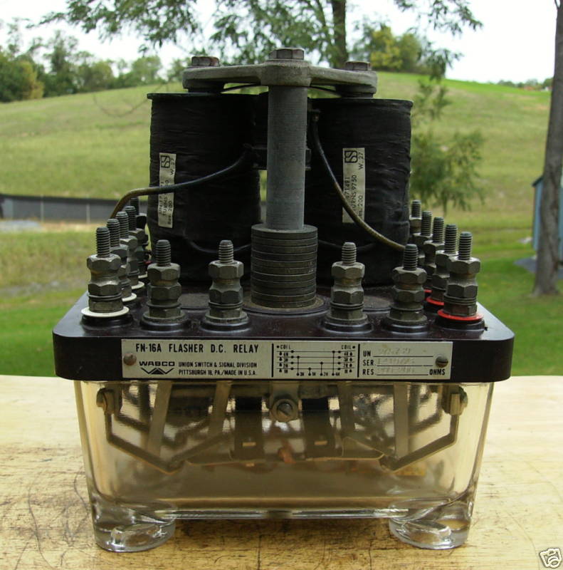
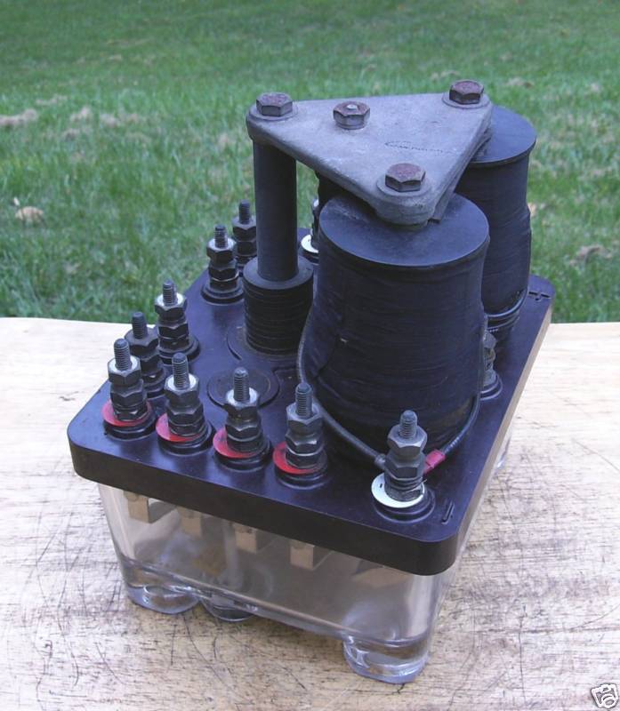
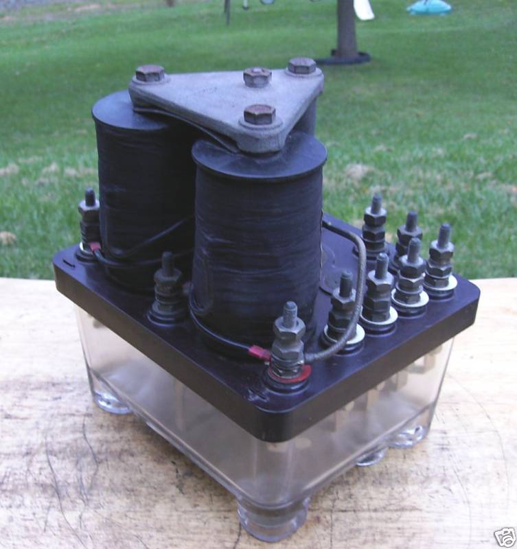
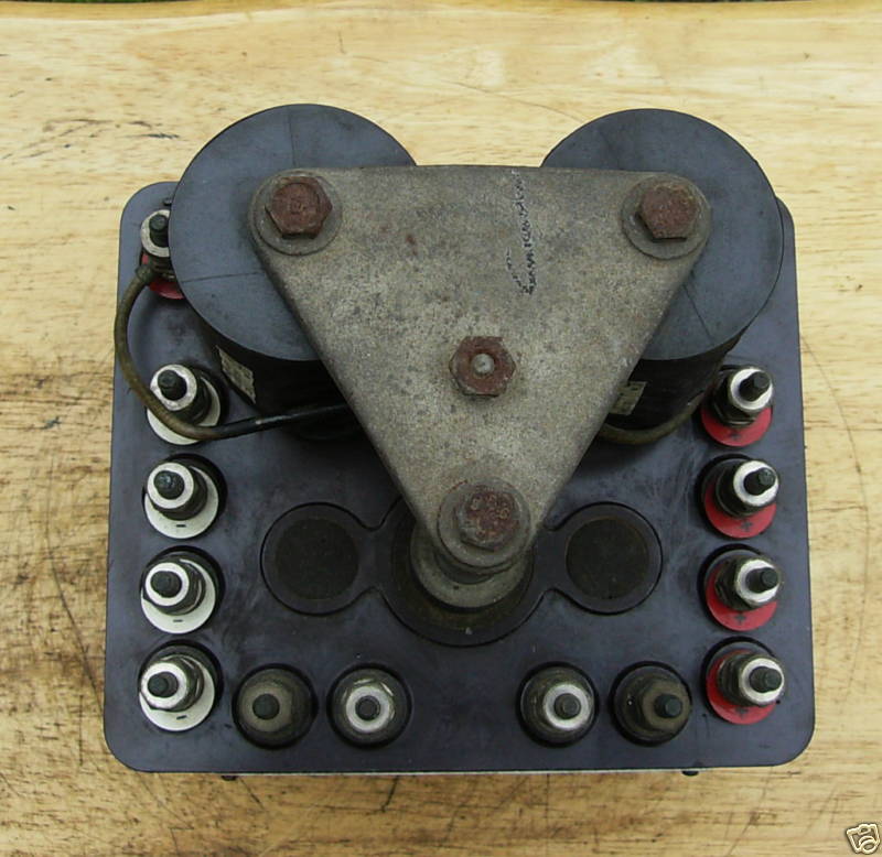
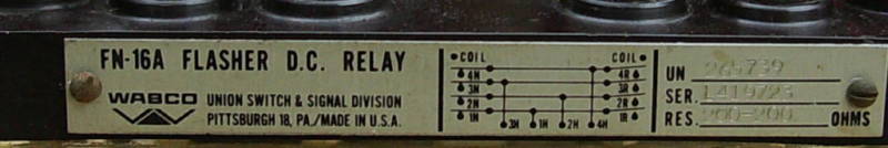
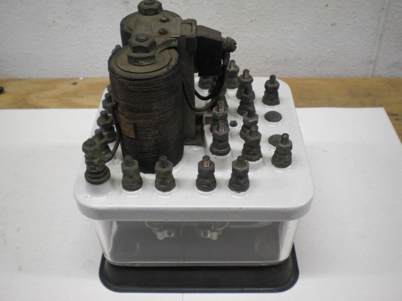
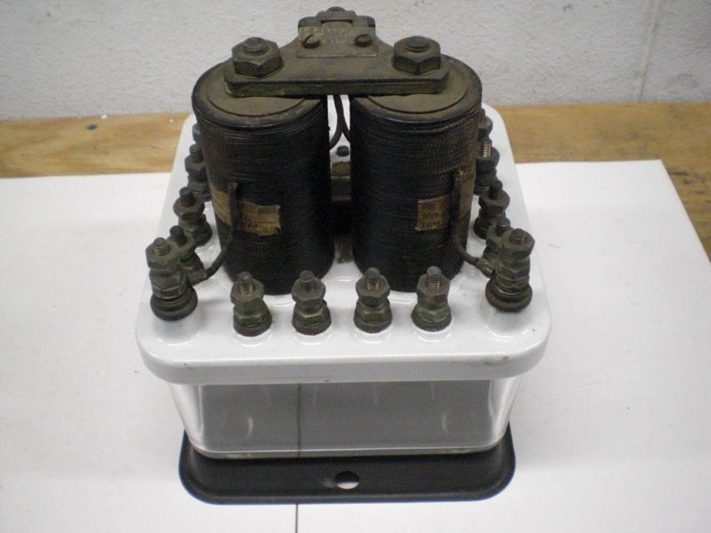
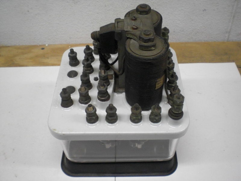
WABCO (US&S)
FN-16A Flasher D.C. Relay
Flasher relays came about
before the advent of solid state electronics, so the designers of these
relays came up with clever mechanical ways to make the armature rock
back and forth magnetically without the need for anything external to
the relay. Working voltage is 6.8 to 8VDC, with a minimum of 6V.
This relay has a four sets of double-throw contacts (4PDT). This
one was set up for 40-45 flashed per minute, and the rate can be changed
by added or removing washers behind a thing called the backstrap.
I've seen prices for these on EBay in the $80-100 range, phew!
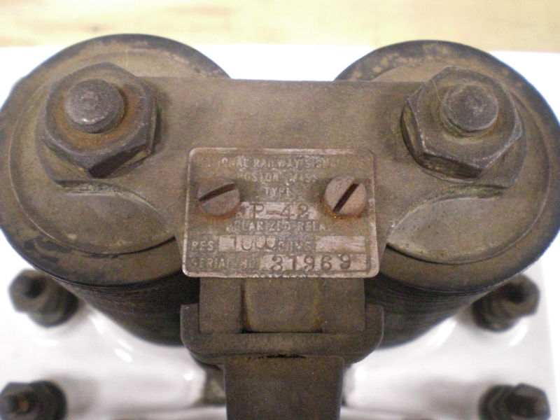
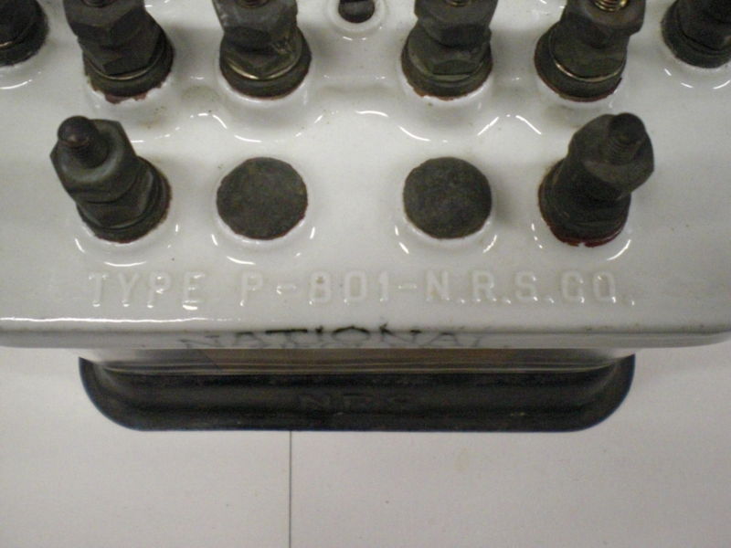
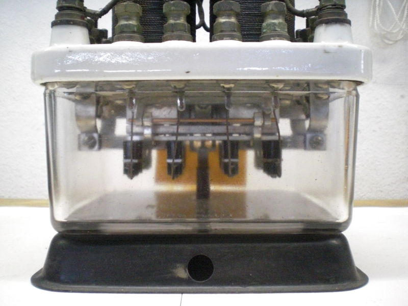
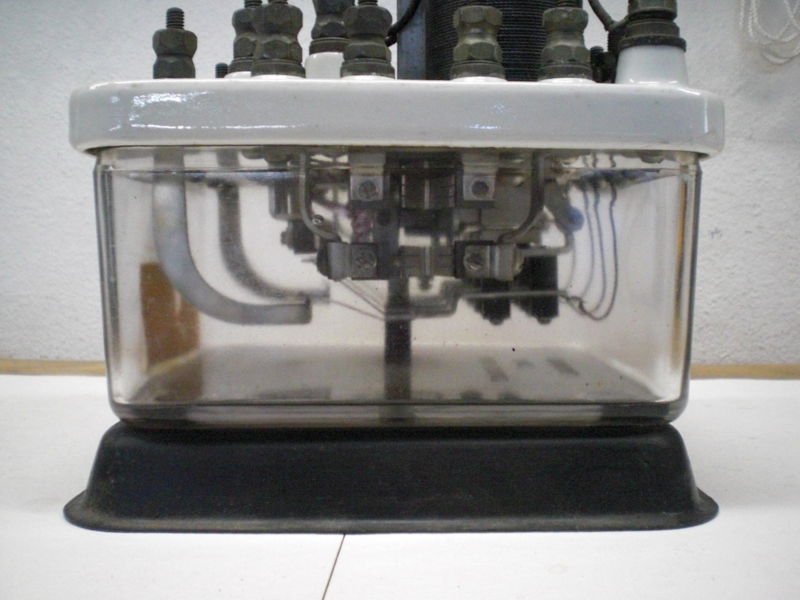
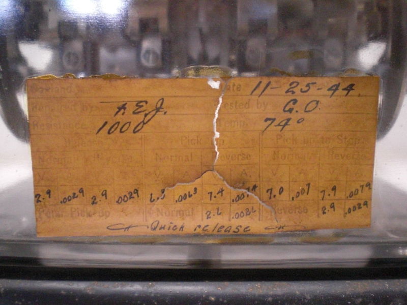
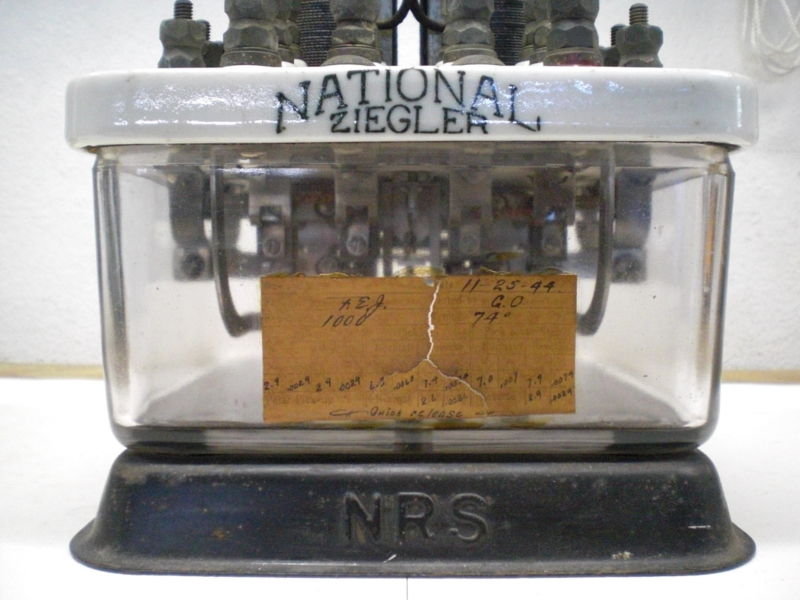
"Zeigler" Model P-42
Polar Relay
According to nameplate,
this is a D.C. polar relay with a 1000 ohm coil, and has 4 sets of
contacts. The starting price for this relay was $149, it sold for
$191.


Comprehensive Relay Terminology List
The terms used on this list are terms suggested by the IEEE and the Association of Relay Manufacturers . It is a fairly long list. This list covers all aspects of relays, not just for the railroad field. Also, I have corrected some obvious mistakes that appeared in the original list
Air Gap – Sometimes used for Contact Separation or for Magnetic Air Gap.
Ampere-Turns – The product of the number of turns in a magnetic coil and the RMS current in amperes passing through the coil.
Armature – A hinged or pivoted moving part of the magnetic circuit in an electromagnetic relay. Sometimes used in general sense to mean any moving part which actuates contacts in response to a change in coil current.
Armature Contact – Sometimes used for Movable Contact.
Armature Relay – A relay operated by an electromagnet which, when energized, causes an armature to be attracted to a pole (or poles).
Auxiliary Relay – A relay which operates in response to opening and closing of its operating circuit to assist another relay or device in performance of a function.
Back Contacts – Same as Normally Closed Contacts. Sometimes used for the stationary contact of single-pole normally closed contacts.
Backstop– The part of a relay which limits movement of the armature away from the pole piece or core.
Backup Relaying – Supplementary relaying designed to operate if a primary relay should malfunction or a circuit breaker fail to operate. Back-up relaying usually disconnects more of the power system than just the part with the faulty element as this is necessary in order to remove the abnormal condition and to minimize effect on the remainder of the system.
Bar Relay – A relay so designed that a bar actuates several contacts simultaneously.
Break-before-make-Contacts – Contacts which interrupt one circuit before establishing, or making another circuit.
Break Contact – Same as Back Contact.
Break Delay – Sometimes used for Release Time.
Bridging – Bridging is a term used to describe a contact transfer in which the movable contact touches the normally open contact before leaving the normally closed contact during the transfer action, thus never completely opening the circuit of the movable contact.
Brush – Sometimes used for Wiper.
Chatter – A sustained rapid opening and closing of contacts caused by variations in the coil current, mechanical vibration and shock or other causes.
Clapper Relay – Sometimes used for Armature Relay.
Close-Differential Relay – Sometimes used for Marginal Relay. Todd Sestero 2/2011
Coil – A magnetic or thermal winding to which energy is supplied to activate the relay.
Contact Arrangement – Contact arrangement referred to the combination of different basic contact forms to make up the entire relay switching structure.
Contact Bounce – Uncontrolled making and breaking of a contact when relay contacts are moved to the closed position.
Contact Follow – The distance two contacts travel together after just touching.
Contact Gap – Same as Contact Separation.
Contact Nomenclature – Each movable contact of a relay constitutes a pole of the relay.
A combination of stationary contact and a movable contact which are engaged when the coil is unenergized is referred to as back, break, form B, or normally closed contacts and is abbreviated as NC.
A combination of stationary contact and movable contact, which are engaged when the coil is energized is referred to as front, form A, or normally open contacts and is abbreviated as NO.
A combination of two stationary contacts and a movable contact which engages one of them when the coil is energized and engages the other when the coil is unenergized is called transfer, form C, or double-throw contacts and is abbreviated as DT.
Contrasted with double-throw contacts, NO and NC contacts are called single-throw contacts, abbreviated as ST.
A combination in which a movable contact simultaneously makes and simultaneously breaks connection between two stationary contacts is called double-break contacts and abbreviated DB. For normally open contacts, this combination may be called double- make contacts.
Relay contact notions are given in the flowing order:
1. Poles
2. Throws
3. Normal Position
4. DB, if double-break or double-break contacts
Example: SPST NO DB designates a single-pole, single-throw, normally-open, double break contacts.
All contacts are single break except when noted as double-break (DB). Relays having several sets of differently functioning contacts will have the contact forms listed in alphabetical order of their letter symbols.
Example: 1A2B refers to SPST NO contacts and DPST NC contacts.
For a relay on which the moving contact engages more than two stationary contacts during its cycle of operation, the contact arrangement is described as MPNT, where “M” is the number of poles, and “N” is the number of throws, e.g., 8P20T
Contact Overtravel – Sometimes used for Contact Follow.
Contact Separation – Maximum distance between mating relay contacts when the contacts are in the open position.
Contact Spring – A current carrying spring to which contacts are fastened. Todd Sestero 2/2011
Contacts – Current carrying parts of a relay which engage or disengage to make or break electrical circuits.
Contactor – Sometimes used for a relay with heavy-duty contacts.
Continuity-Transfer Contacts – Same as Make-Before-Break contacts.
Continuous Duty Relay – A relay which may be energized with rated coil voltage or current at rated contact load for a period of three (3) hours or more without failure and without exceeding specified temperature requirements.
Current Balance Relay – A relay that allows tripping whenever there is an abnormal change in the division of current between two circuits.
Current Rating – See Rated Coil Current and Rated Contact Current.
Current Relay – A relay which is designed to operate at a particular rated coil current rather than at a rated coil voltage.
Cycle Timer – A controlling mechanism which opens or closes contacts according to a preset cycle.
Deenergize – To deenergize a relay is to disconnect the relay coil from its power source.
Definite-Purpose Relay – A readily available relay which has some electrical or mechanical feature which distinguishes it from a general purpose relay. Types of definite purpose relays are interlock, selector, stepping, sequence, latch-in, and time-delay.
Delay Relay – A relay that is intentionally designed for a time delay between the energizing or deenergizing instant and the time that the relay contacts open or close.
Differential Relay – A relay having multiple windings which functions when the voltage, current, or power difference between windings reaches a predetermined value.
Directional Relay – A relay that allows for tripping for current flow in one direction only.
Double-Break Contacts – See Contact Nomenclature.
Double-Make Contacts – See Contact Nomenclature.
Double Throw Contacts – See Contact Nomenclature.
Double-Wound Coil – A double-wound coil is a coil winding consisting of two parts wound on the same core.
Drop-Out Values – Drop-out current, voltage, or power is the maximum value for which contacts of a previously energized relay will always assume their unenergized positions.
Duty Cycle – Rated working time of a device compared to its idle time.
Electric Reset – A qualify term applied to a relay indicating that following an operation its contacts must be reset electrically to their original positions.
Electromagnetic Relay – A relay whose operation involves the use of a magnetic field which is produced by an electromagnet.
Electrostatic Spring Shields – Metallic shields between two relay springs to minimize the capacitance between them.
Enclosed Relay – A relay which has both the coil and contacts protected from the surrounding medium by a cover that is not airtight. Todd Sestero 2/2011
Energize – To energize a relay is to apply a rated voltage to its coil.
Extension Spring – Same as a Restoring Spring.
Fast-Operate Relay – A high speed relay specifically designed for short operate time but not short release time.
Fast-Operate, Fast-Release Relay – A high speed relay specifically designed for both short operate time and short release time.
Fast-Operate, Slow-Release Relay – A relay designed specifically for short operate time, but not for a short release time.
Fast-Release Relay – A high speed relay specifically designed for short release time but not for a short operate time.
Fixed Contacts – Stationary contacts of a relay which are engaged and disengaged by moving contacts to make or break circuits.
Flight Time – Sometimes used for Transfer Time.
Follow-Through Contacts – Contacts which have contact follow.
Frame – The structure on which the coil and contact assembly are mounted.
Front Contacts – Sometimes used for the moveable contact of a single-pole normally open contacts (also see Contact Nomenclature).
Front Contacts – Same as Normally Open Contacts. Todd Sestero 2/2011
Gasket-Sealed Relay – An airtight relay, the sealing of which involves the use of a gasket which is not bonded to the other sealing material.
General-Purpose Relay – A readily available relay which has the design, construction, operational characteristics, and ratings such that it is acceptable to a wide variety of uses.
Hand-Reset – A qualifying term applied to a relay indicating that following an operation, the contacts must be manually reset to their original positions.
Header – The part of a hermetically sealed relay through which the electrical terminals pass.
Hermitically Sealed Relay – An airtight relay, the sealing of which involves fusing or soldering but does not use a gasket.
High-Speed Relay – A relay specifically designed for a short operate time, release time, or both.
Hold Values – The hold current, voltage, or power is the minimum value for which contacts of a previously energized relay will always maintain their energized position.
Homing– Homing is a qualifying term applied to a stepping relay indicating that wipers, upon completion of an operational cycle, are stepped around or back to the start position.
Hum – Hum, as applied to relays, is the sound caused by mechanical vibration resulting from alternating current flowing through the coil.
Impregnated Coils – Coils which have been permeated with phenolic or similar varnish to protect them from mechanical vibration, handing, fungus, and moisture.
Inductive Winding – An inductive winding, as contrasted with a noninductive winding, is a coil with inductance.
Instrument Relay – A relay, the operation of which depends upon principles employed in electrical measuring instruments such as the electrodynamometer, iron-vane, and D’Arsonval.
Interlock Relay – A relay composed of two or more coils with their armatures and associated contacts so arranged that the freedom of one armature to move or its coil to be energized is dependent upon the position of the armature.
Intermittent-Duty Relay – A relay which must be deenergized at occasional or periodic intervals to avoid excessive temperature.
Latch-In Relay – A relay having contacts which lock in either the energized or deenergized position until reset manually or electrically.
Level – As applied to a stepping relay, the term level is used to denote one bank or series of contacts.
Level Contact – Sometimes used for Movable Contact.
Locking Relay – Sometimes used for Latch-In Relay.
Low-Capacitance Contacts – A type of contact construction providing low inter-contact capacitance.
Magnetic Air Gap – A magnetic air gap is a nonmagnetic portion of a magnetic circuit.
Magnetic Freezing – The sticking of a relay armature to the core, after deenergization, due to residual magnetism of the core.
Magnetic Switch – Sometimes used for Relay.
Make-Before-Break Contacts – Double throw contacts so arranged that the moving contacts establishes a new circuit before disrupting the old one.
Make Delay – Sometimes used for Operate Time.
Marginal Relay – A relay which functions in response to predetermined changes in the value of a coil current or voltage.
Mercury-Contact Relay – A relay in which the contact medium is mercury.
Motor-Driven Relay – A relay which is actuated by rotation of the shaft of some type of motor, for example, a shaded-pole, induction-disk, or hysteresis motor.
Movable Contact – A contact which, when the relay is energized or deenergized, is mechanically displaced to engage or disengage one or more stationary contacts.
Multiple-Break Contacts – Contacts so arranged that, when they open, the circuit is interrupted in two or more places.
Multiple Pile-up – An arrangement of contact springs which is composed of two or more separate pile-ups.
Multiple Stack – Same as Multiple Pile-up. Todd Sestero 2/2011
Neutral Relay – A neutral relay, in contrast to a polarized relay, is a relay in which the movement of the armature is independent of direction of flow of current through the relay coil.
Non-Bridging – A term used to describe a contact transfer in which the movable contact leaves one contact before touching the next.
Non-Homing – A qualifying term applied to a stepping relay indicating that the wipers, upon completion of an operational cycle, do not return to the home position, but are at rest on the last used set of contracts.
Non-Inductive Windings – A type of winding in which the magnetic fields produced by two parts of the winding cancel each other and provide a non-inductive resistance.
Non-Magnetic Shim – A non-magnetic material attached to the armature or core of a relay to prevent iron-to-iron contact in an energized relay.
Non-Operate Value – The non-operate voltage, current, or power is the maximum value for which contacts of a previously deenergized relay will always maintain their deenergized positions.
Normal Position – Deenergized position, open or closed, of contacts due to spring tension or gravity.
Normal Sequence of Operation – The sequence in which all normally closed contacts open before closure of normally open contacts of the assembly.
Normal-Speed Relay – A relay in which no attempt has been made either to increase or decrease the operate time or the release time.
Normally Closed Contacts – A combination of a stationary contact and movable contact which are engaged when the coil is deenergized.
Normally Open Contacts – A combination of a stationary contact and a movable contact which are not engaged when the coil is deenergized.
Off-Limit Contacts >– Contacts on a stepping relay used to indicate when the wiper has reached the limiting position on its arc and must be returned to normal before the circuit can function again.
Off-Normal Contacts – Stationary contacts on a homing stepping relay used to indicate when the wiper is not in the starting position.
Operate Time – If a relay has only normally closed contacts, its operate time is the longest time interval given by definition (a) below. If a relay has normally open contacts (regardless of whether or not it has normally closed contacts), its operate time is the longest time interval given by definition (b).
Operate Time For Normally Closed Contacts – Operate time for NC contacts is the total elapsed time from the instant the coil is energized until the contacts have opened; i.e., contact current is zero.
Operate Time For Normally Open Circuits – Operate time for normally open contacts is the total elapsed time from the instant the coil is energized until the contacts are closed and all contact bounce has ceased.
Operate Values – Same as Pick-up Values.
Operating Frequency – The rated A-C frequency of the supply voltage at which the relay coil is designed to operate.
Overload Relay – A relay which is specifically designed to operate when its coil current reaches a predetermined value above normal.
Overvoltage Relay – A relay which is specifically designed to operate when its coli voltage reaches a predetermined value above normal. Todd Sestero 2/2011
Partially Enclose Relay – A relay which has either contacts or coil (but not both) protected from the surrounding medium by a cover that is not airtight.
Partially Sealed Relay – A relay which has either contacts of coil (but not both) sealed.
Pick-Up Values – Pick-up voltage, current, or power is the minimum value for which contacts of a previously deenergized relay will assume their energized position.
Pile-Up – A set of contact arms, assemblies, or springs placed one on top of the other with insulation between them.
Plunger Relay – A relay operated by energizing an electromagnetic coil, which in turn operates a movable core or plunger by solenoid action.
Polarized Relay – A relay which is dependent upon the polarity of the energizing current to operate.
Pole – See Contact Nomenclature.
Pole-Face – The pole face is the part of the magnetic structure on the end of the core nearest the armature.
Pull-In Values – Same as Pick-Up Values.
Pull-On Values – Sometimes used for Pick-Up Values.
Ratchet Relay – A stepping relay actuated by an armature-driven ratchet.
Rated Coil Current – Steady-state coil current at which the relay is designed to operate.
Rated Coil Voltage – Coil voltage at which the relay is designed to operate.
Rated Contact Current – Current which the contacts are designed to carry for their rated life.
Relay – A device which is operated by variation in conditions of one electric circuit to affect the operation of other devices in the same or other electric circuits by either opening circuits, closing circuits, or both.
Release Factor – Is a ratio, expressed in percent, of drop-out current to rated current or the analogous voltage ratio.
Release Tine – If a relay has only NO contacts, the release time is the longest time interval given by definition (a) below. If a relay has NC contacts (regardless of whether or not it has NO contacts) its operate time is the longest time interval given by definition (b).
Release Time For Normally Open Contacts – Release time for NO contacts is the total elapsed time from the instant the coil current starts to drop from its rated value, until the contacts have opened; i.e., contact current is zero.
Release Time For Normally Closed Circuits – Release time for NC contacts is the total time from the instant the coil current starts to drop from its rated value until the contacts are closed and all contact bounce has ceased.
Release Values – Same as Drop-Out Values. Todd Sestero 2/2011
Repeating Timer – A timing device which upon completion of one operating cycle, continues to repeat automatically until excitation is removed.
Residual Gap – The length of the magnetic air gap between the pole-face center and the nearest point on the armature when the armature is in the energized position.
Residual Pins or Screws – Nonmagnetic pins or screws attached to either the armature or core of a relay to prevent the armature from directly contacting the magnetic core.
Residual Setting – Value of the residual gap obtained by the use of an adjustable residual screw.
Residual Shim – Same as Non-Magnetic Shim.
Restoring Spring – A spring which moves the armature to and holds it in the normal position when the relay is deenergized.
Retractile Spring – Sometimes used for Restoring Spring.
Rotary Relay – Sometimes used for Motor-Driven Relay.
Rotary Stepping Relay – Same as Stepping Relay.
Rotary Stepping Switch – Same as Stepping Relay.
Sealed Relay – A relay which has both coil and contacts enclosed in an airtight cover.
Self-Cleaning Contacts – Sometimes used for Wiping Contacts.
Selector Relay – A relay capable of automatically selecting one or more circuits from a number of circuits.
Sequence Control – Automatic control of a series of operations in a predetermined order.
Sequence Relay – A relay which controls two or more sets of contacts in a definite predetermined sequence.
Shading Coil – Sometimes used for Shading Ring.
Shading Ring – A shorted turn surrounding a portion of a pole of an alternating current magnet, causing a delay of change of magnetic flux in that part, thereby preventing contact chatter.
Slave Relay – Sometimes used for Auxiliary Relay.
Slow-Operate, Fast-Release Relay – A relay specifically designed for long operate time and short release time.
Slow-Operate Relay – A slow speed relay which has been specifically designed for long operate time but not for long release time.
Slow-Operate, Slow –Release Relay - A relay specifically designed for both long operate time and long release time.
Slow-Release Relay - A slow speed relay which has been specifically designed for long release time but not for long operate time.
Slow-Speed Relay – A relay specifically designed for long operate time, release time, or both. Todd Sestero 2/2011
Slug – A highly conductive sleeve placed over the core to aid in retarding the establishing or decay of Flux within the magnetic path.
Solenoid Relay – Sometimes used for a Plunger Relay.
Solid State Relay – Relays that use various low-power components – diodes, transistors, and thyristors, and associated resistor and capacitors. These components are designed into logic units used in many ways.
Special Purpose Relays – A relay which has an application that requires special features which are not characteristic of conventional general-purpose or definite-purpose relays.
Specified Duty Relay – A relay which is designed to function with a specified duty cycle, but which might not be suitable for other duty cycles.
Spring Buffer – A bearing member made of insulating material which transmits motion of the armature to the movable contact and from one movable contact to another in the same pile-up.
Spring Pile-Up – Same as Pile-Up.
Spring Stud – same as Spring Buffer.
Stack – Same as Pile-up.
Stationary Contact – A contact member which is rigidly fastened to the relay frame and which is not moved as a direct result of energizing or deenergizing the relay.
Stepping Relay – A relay whose contacts are stepped to successive positions as the coil is energized in pulses. Some stepping relays may be stepped in either direction. (The Stepping Relay is also called a Rotary Stepping Switch or a Rotary Stepping Relay).
Telephone-Type Relay – Sometimes used for an armature relay with an end-mounted coil and spring pile-up contacts mounted parallel to the long axis of the relay coil.
Tension Spring – Sometimes used for Restoring Spring.
Thermal Relay – A relay which is operated by the heating effect caused by electric current flow.
Throw – See Contact Nomenclature.
Time-Delay Relay – A relay in which a delayed action is purposely introduced.
Timing Relay – A motor driven time-delay relay.
Transfer Time – Total elapsed time between the breaking one set of contacts and the making of another set of contacts.
Transfer Time on Operate – Transfer time on operate is the total elapsed time from the instant the NC contacts start to open until the NO contacts are closed and all contact bounce has ceased.
Transfer Time on Release – Transfer time on release is the total elapsed time from the instant the NO contacts start to open until the NC contacts are closed and all contact bounce has ceased.
Transit Time – Same as Transfer Time.
Trip values – Trip voltage, current, or power is rated value at which a bistable polarized relay will transfer from one contact to another.
Undercurrent Relay – A relay specifically designed to function when its coil current falls below a predetermined value.
Undervoltage Relay – A relay specifically designed to function when its coil voltage falls below a predetermined value.
Unenclosed Relay – A relay which does not have its contacts or coil protected from the surrounding medium by a cover.
Winding – Same as Coil. Todd Sestero 2/2011
Wiper – A moving contact on a stepping relay.
Wiping Contacts – Contacts designed to have some relative motion during the interval from the instant of touching until completion of the closing motion.
Last Updated: 11/18/2019