RAILROAD
SIGNALS
of the
U.S.
AUXILIARY SIGNAL SUPPORT EQUIPMENT
Towers
Equipment Cabinets
Rod Mechanisms
Junction Boxes
Battery Boxes
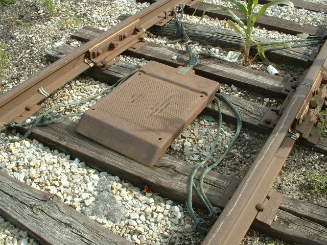
Impedance Bonds
Compressor and Air Systems
RAILFAN GUIDES HOME
RAILROAD SIGNALS HOME
This section covers other signal related items such as equipment cabinets, battery boxes, etc., that without them, signals would not be able to function.
At The Top Of The Page: A relay cabinet and battery box along the Baltimore Light Rail R-O-W in Linthicum MD, across the tracks from the B&A Maple Road station.
As always, if you have something to add or correct, please check hereTowers
Towers are now included in with the stations section, the
index page is
here
Relay Boxes / Equipment Cabinets
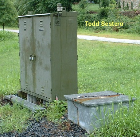
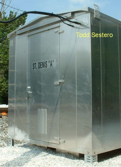
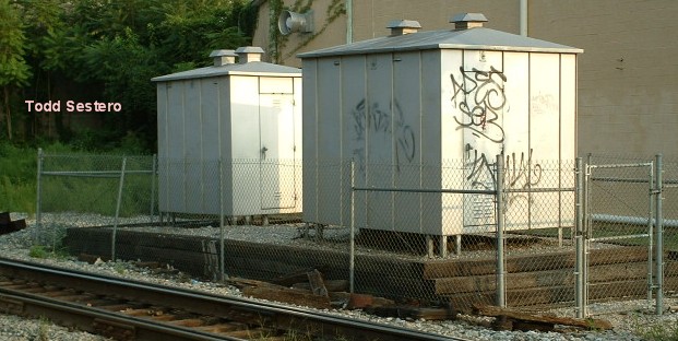
Equipment cabinets house all of the necessary electrical equipment for a particular installation, whether it be for relays that control the signals, telephone equipment, or radios. Batteries are generally not kept in these cabinets because of the possibility of fires.
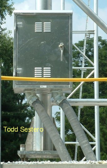
These structures can be big or small. They can be mounted on the ground, mounted on a concrete slab, mounted on a wood foundation, mounted to a wall, mounted on a pole, or mounted to some other support structure such as the signal bridge or other convenient structure to save the cost of a separate installation.
Older installations employed housing that were made of steel, with newer ones being made of aluminum because they do not rust or need to be painted. You could also find wooden and concrete used for the purpose, although today, these are rare sights.
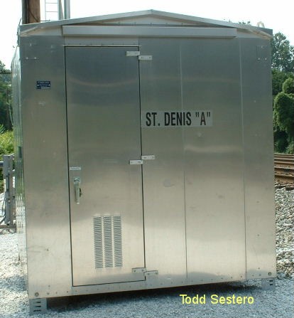
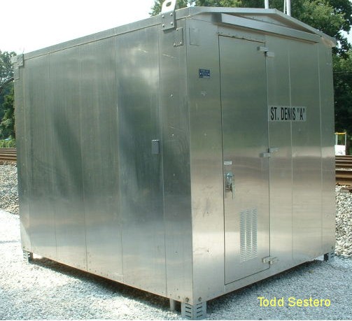
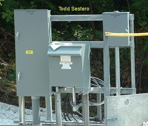
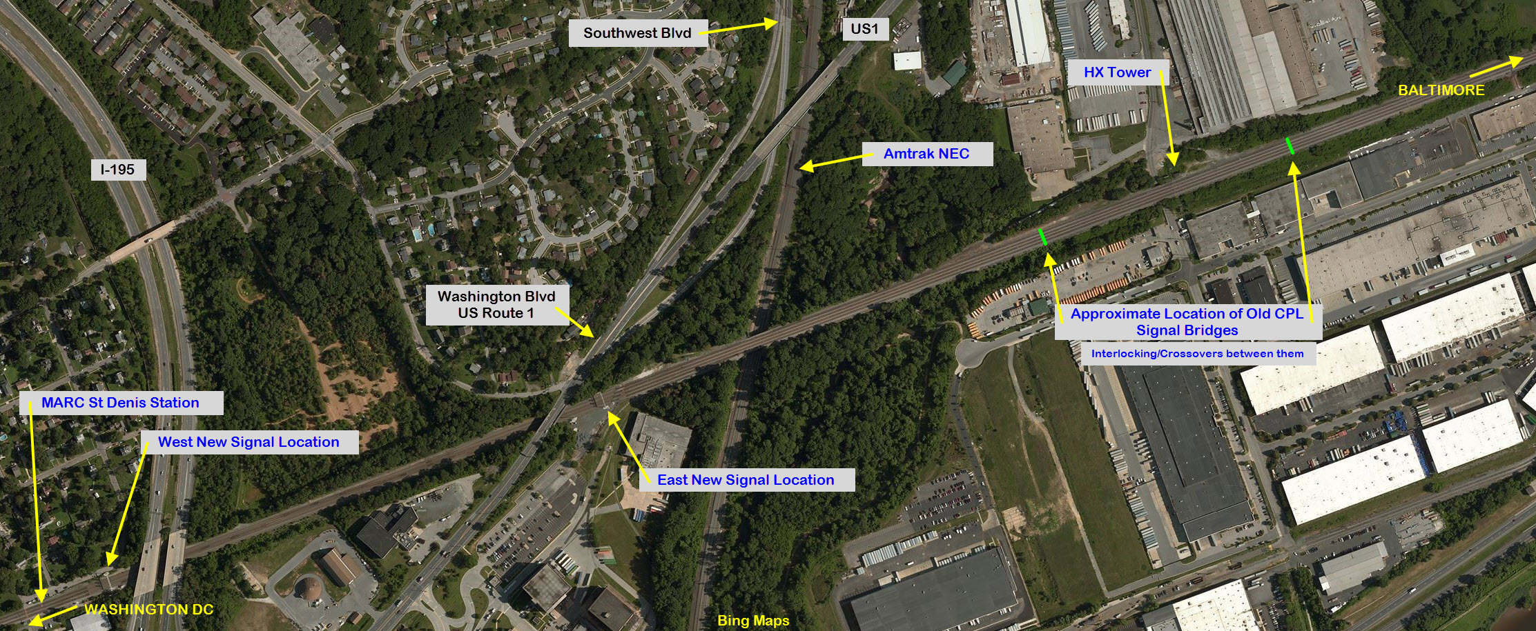
Relay / St Denis MD
This is a new installation where signals did not exist before. CSX realigned the tracks and interchange on the approach to St. Denis coming from the Baltimore side. This prompted them to install a couple of new signal bridges on either side of the Washington Blvd overpass. This is the equipment cabinet for the one on the south side. Pictures taken in August of 2005. Once the trackwork was done, and the signals here were placed into service, the two old CPL signal bridges on either side of HX tower were taken down.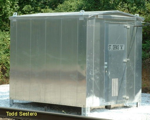
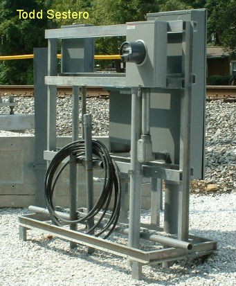
Rod Mechanisms
Battery boxes are used to separate batteries from the equipment they power. came about because batteries were, and still are, a hazardous item in terms of the hydrogen they can give off
during normal operation. Hydrogen, as you may know, is a extremely flammable element, as pictures of the Hindenburg back in the 1930's can attest. Because the smallest spark or bit of static electricity can cause the hydrogen
to explode, batteries have ALMOST always been separated from the apparatus they are used to support. Impedance bonds are used to electrically isolate sections of rail, or track, from each other, for the purposes of signaling. They allow the DC traction power to flow through them, but they
block the signals used to actuate the relays. Mason City IA Turnouts, or switches, can be operated by a
variety of methods. They can be manually thrown, or they can be remotely
activated thru the use of electricity and/or pneumatics. When switches are
controlled by air, a source of high air pressure is needed. You still need
sort sort of electrical control, but the power requirement is not as great since
the power to move the points is supplied by the air pressure. You only
need enough voltage and current to control small air valves. Disclaimers: I love trains, and I love signals. I am not an
expert. Please Note:
Since the main focus of my two websites is railroad signals, the railfan guides
are oriented towards the signal fan being able to locate them. For those
of you into the modeling aspect of our hobby, my
indexa page has a list of
almost everything railroad oriented I can think of to provide you with at least a few pictures to
help you detail your pike. If this is a railfan page, every effort has
been made to make sure that the information contained on this map and in this
railfan guide is correct. Once in a while, an error may creep in :-)
:-)
My philosophy: Pictures and maps are worth a
thousand words, especially for railfanning. That's why my guides
are the way they are :-) Beware: If used as a source, ANYTHING from Wikipedia must be treated as
being possibly being inaccurate, wrong, or not true.
RAILFAN GUIDES HOME
The charging and discharging cycle causes small amounts of hydrogen to be released from the acid in the batteries. This is one of the reasons signal maintainers need to check the specific gravity
of the batteries. We used to have to check the same things on the batteries in our cars, although newer batteries seem to require less maintenance of this type.
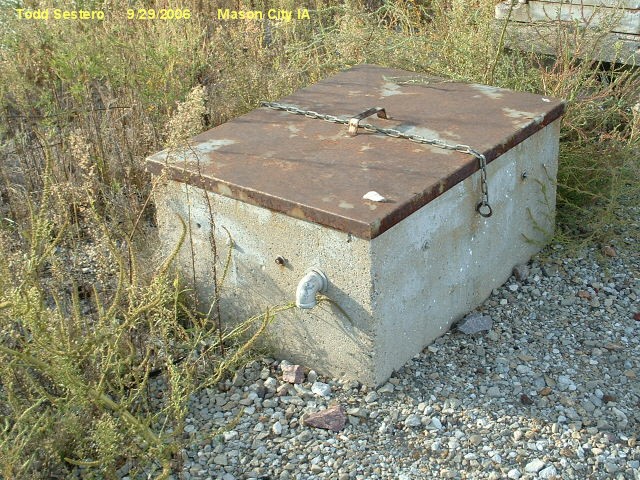
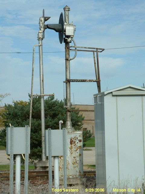
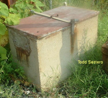
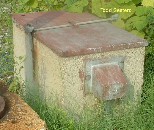
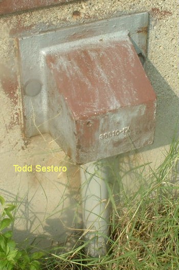
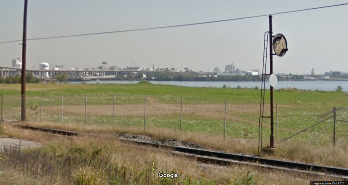
Mason City IA on the UP
A battery box (and it's signals) providing back-up at the diamond with the Iowa Traction, pix from 2006.
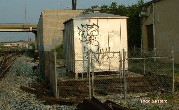
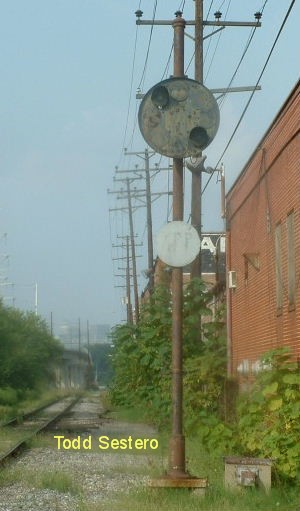
Baltimore MD on CSX, formerly the B&O
A battery box used to support a single CPL signal with a single aspect.... BTW, it is the only signal that did not get replaced in the replacement upgrade of 2012.
When trains or transit use power from the rails to operate, it is all but impossible to superimpose another small DC level on top of that to actuate relays. So
what do they do. Someone eventually figured out that an AC signal, superimposed on the tracks and/or rails could be used to accomplish the same thing, but then they also needed a way to separate the AC signals from the DC or
AC traction power. So the impedance bond came to be.
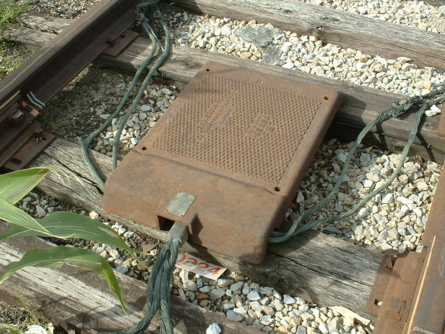
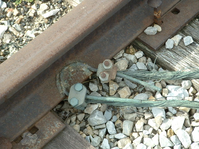
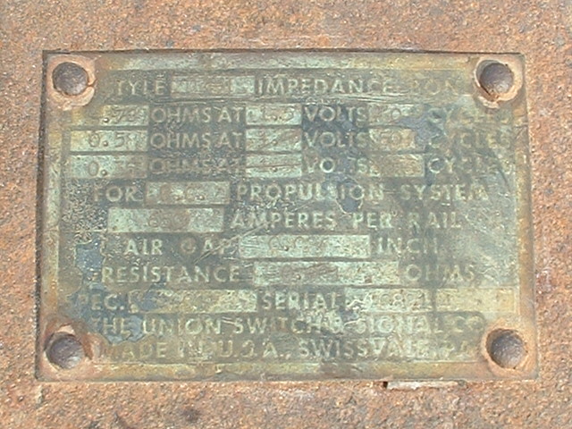
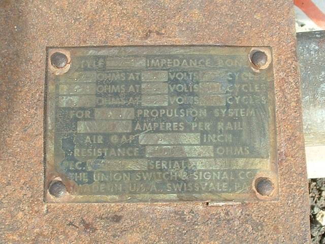
Impedance bonds operate on the principle that an impedance of a certain value can be used to block, stop, or shunt an AC signal of a specific frequency or band of frequencies. Ham radio
operators use a thing called a "trap" to allow a piece of wire or antenna to operate at more than one frequency, by blocking the RF signal access to the rest of the wire. If you have a
multi-band scanner antenna, it likely has a trap or two to do the same thing - the higher frequencies do not use the whole length of the antenna due to the traps.
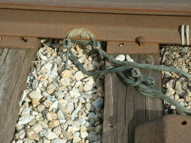
They are also used to prevent the AC signals from getting back into the power source. This example uses overhead wire such as used by theIowa Traction,
or the many light rail systems that use overhead power. The drawing below illustrates the basic principle. 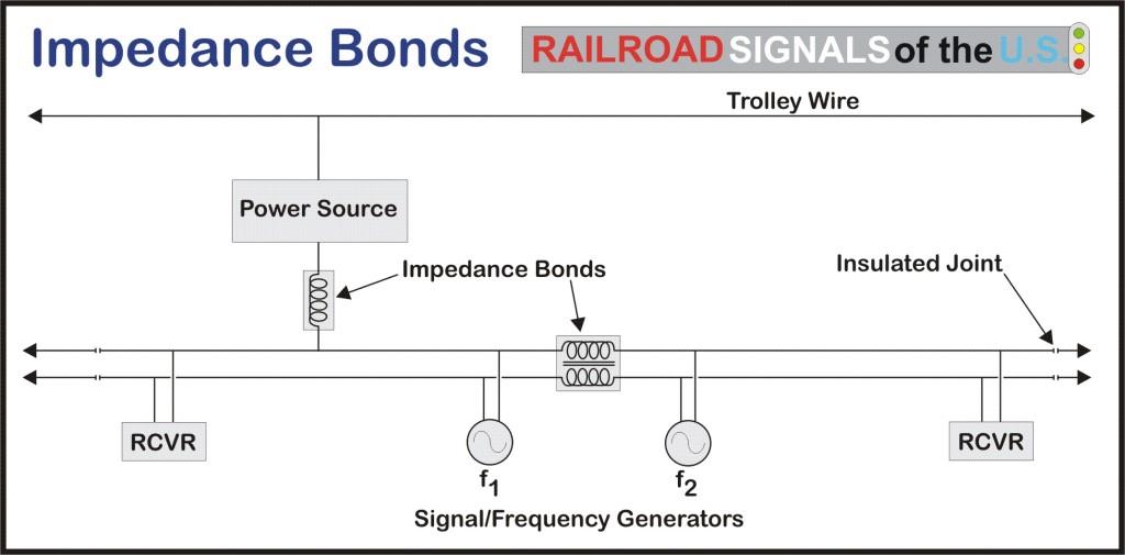
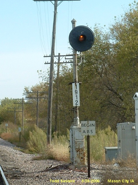
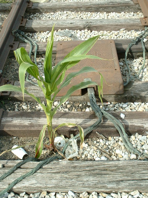
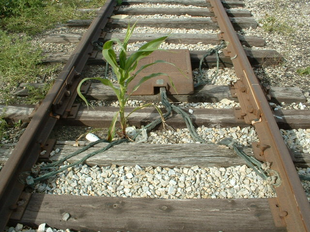
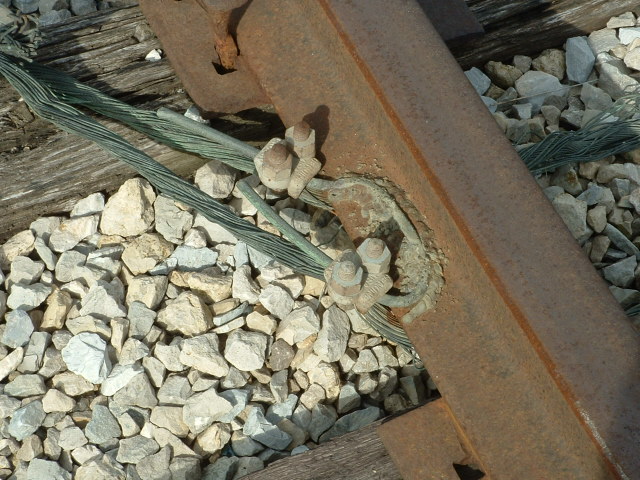
An older installation on the Iowa Traction, on the eastern side of a diamond with the Union Pacific on the south side of town. Pictures are from a trip
to Minneapolis in 2006. In case you can't tell, I like the corn growing in the middle of the tracks! :-) :-)
By the way, floobydust is
a term I picked up 30-40 years ago from a National Semiconductor data
book, and means miscellaneous and/or other stuff.
Pictures and additional information is always needed if anyone feels
inclined to take 'em, send 'em, and share 'em, or if you have
something to add or correct.... credit is always given! BE NICE!!! Contact info
is here
RAILROAD SIGNALS HOME
New 8-31-2005
Last messed with
04 Nov 2016