Train Order signals from a 1969 B&O/C&O Rulebook
RAILROAD SIGNALS of the U.S.
TRAIN CONTROL METHODS
by (mostly) SIGNALS
RAILFAN GUIDES HOME
RAILROAD SIGNALS HOME
Pictures and additional info is always needed if anyone feels inclined to take 'em, send 'em, and share 'em, or if you have something to add or correct.... credit is always given! Contact info is here
Manual
In a Manual Block System, the operators at the
Block Stations keep track of the location of all trains (by keeping a record, a
"block sheet") moving between Block Stations, and will admit only one train at a
time into a "block" between stations.
Before he was permitted to admit a train to a block at one end of the block,
call it A, the operator was required to call the operator at the other end of
the block, call it B, and "obtain the block." When the train cleared B,
the operator at B would call the operator at A and report the train clear of the
block. Each operator kept meticulous records of time the block was given
and the time it was cleared. A semaphore was used at each station to
indicate "Block Clear" or "Block Occupied."
But "Manual Blocking" was only a "second order" of protection. The
underlying authority for the movement of trains was still the Time Table-Train
Order system, and the fundamental protection for the prevention of rear-end
collisions was still Rule 99 flagging. So we can rightfully say that
Manual Blocking was another layer of protection superimposed on the Time
Table-Train Order method of operation.
The idea for dividing the railroad into blocks, and permitting only one train in
a block at a time, was conceived in 1865 by Ashbel Welch, Superintendent of the
Camden & Amboy RR and the Belvidere-Delaware Railroad. Under separate
cover I'll forward a PDF of a paper he read in New York in 1866, called "Safety
Signals," detailing his idea. (The British may dispute Welch's claim for
originating the concept.) Welch implemented his "block" concept on his two
railroads in 1865.
The Pennsylvania Railroad chose to adopt Welch's Manual Block System in
preparation for the great deluge of traffic it saw coming in connection with the
Centennial Exhibition at Philadelphia in 1876. In late 1874, the PRR began
erecting "block stations" equipped with "block signals" on the entire Main Line
from Pittsburgh to Philadelphia. (This was the origin of the "signal
tower.") The signals they used for this, however, were "Banner Box"
signals, not semaphores. I'll also attach a photo of a Banner Box Signal.
The benefit the PRR obtained from its initial installation of the Manual Block
System was in the prevention of rear-end collisions (not head-on collisions,)
for the PRR already had a double track system where trains ran in only one
direction on a given track. The system worked so well that it was later
extended to single track branch lines. But as I wrote yesterday, it was
1920 before Manual Blocking was implemented on some branches.
It is sometimes said that Block Stations were located about every five miles on
the PRR. To test that notion, I once used my research notes to calculate
the number of Block Stations which once existed on the busy PRR line between
Rockville at Harrisburg, and Renovo. I counted the number of Block
Stations and and divided that into the number of miles, and found that the
average distance between Block Stations was 5.1 miles !
Maintaining a system of Manual Block stations was, of course, labor intensive
and expensive, even if the operators did work 12 hours per day. There were
several things which led to its demise (and here I shall speak only of the PRR.)
First, the PRR suffered a very bitter strike with its telegraphers in 1902, and
thereafter embarked on a crash program of installing telephones, and skilled
telegraphers were no longer needed for the Manual Block System to work.
Second, an Hours of Service law was passed in 1907, restricting railroad
telegraphers to working only 9 hours per day (which meant that a station
formerly manned by two men working twelve hours shifts, would thereafter require
three men working eight-hour shifts.)
Of course, the obvious improvement was the installation of Automatic Block
Signals, which system had been perfected since the 1890s. But on branch
lines with lighter traffic, where the high capital cost of installing automatic
signals was not warranted, the PRR used another tack. Beginning in 1920,
they closed a number of their manned block stations, replaced them with a
"Block-Limit Signal" and a nearby telephone. An open (manned) Block
Station might be "in charge of" three or four such Block-Limit Signals.
Trains were required to stop at these Block-Limit Signals and use the telephone
to obtain the "condition of the block ahead" (which permission was recorded on
the infamous form called a "K Card.") After passing a Block-Limit Signal,
the train stopped and the Conductor got off and telephoned the Block Station
which was "in control" and reported his train past the Block-Limit Signal.
I'll also attach a photo of a Block-Limit Signal.
This is only a bare-bones sketch of the system. There were all kinds of
permutations, such as the "Permissive Block Indication" which allowed "a train,
other than a passenger train, to follow a train, other than a passenger train"
into a block, moving prepared to stop. Another permutation provided for
admitting opposing trains to a block when they were to meet at an intermediate
siding between open Block Stations.
The preceding was a short discussion of Manual
Block Operation by a friend who wishes to remain anonymous, but he knows who he
is and I thank him!
Train Orders
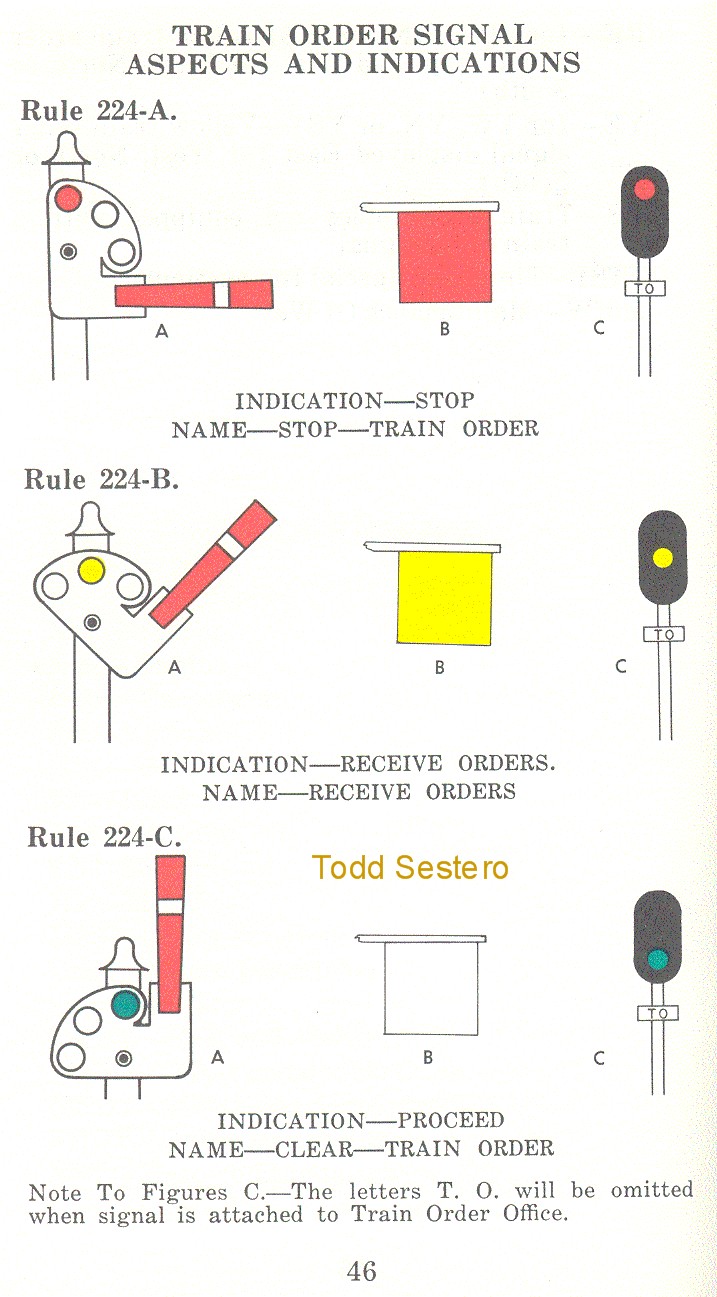
Train Orders are written instructions for the train crew to follow. They were given to the train crew at stations and towers.
Many railroads adopted some form of signal for the train to tell the engineer if he needed to stop or slow down to receive the orders, or neither. If the train order signals were green, the train did not have to stop. If the signal was at yellow, he needed to slow down, and the orders would be passed on by placing the papers in a hoop, and the conductor would grab them as the train went by. If the signal was red, the train had to stop to receive the signals.
Most of the signals shown below are semaphores. Prior to semaphores, many railroads used some sort of banner that rotated, similar to a switch stand target with the red and green. With some of these, there was only one banner painted red, which when swung perpenducular to the track, the engineer would stop the train. Some employed two so that white would show when the train did not have to stop.
Some railroads, after semaphores, went to using color light signals. Some railroads, such as the Western Maryland Rwy, used standard traffic light signals for the purpose, since the requirements were not as strict as those for wayside signals.
Train Order signals from a
1969 B&O/C&O Rulebook

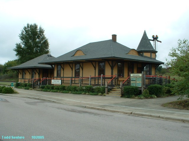
Train Order Semaphore
at the
North Carolina Transportation Museum/Spencer NC.
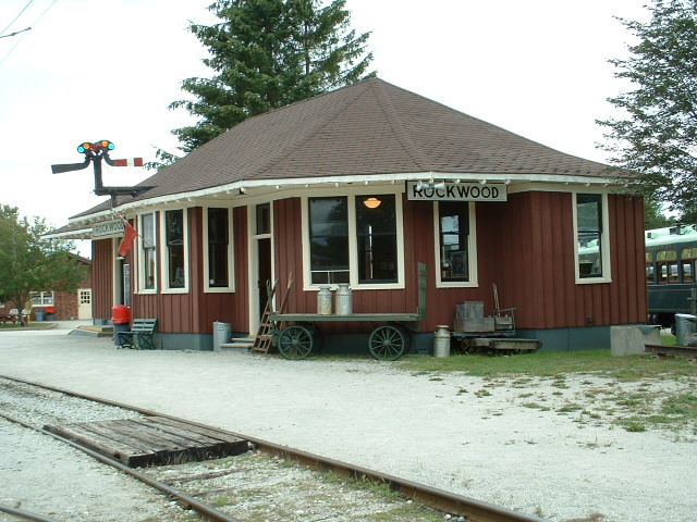

Train Order Semaphore
at the
Radial Railway Museum in Milton ONT.
Track Warrant Control (TWC)
A Tack Warrant is a verbal form of authorization, used to authorize trains to occupy the main tracks. Orders are usually given by radio. TWC is a verbal authorization system defined by the General Code of Operating Rules (GCOR).
Track Warrants can be used as a standalone dispatching and safety system in unsignaled territories, or can be supplemented with ABS to increase flexibility and traffic capacity.
The dispatcher reads the track warrant info (and instructions) to a crew member of a train, who then writes the information down on a form standardized by the railroad. The same crew member then reads back the info back to the dispatcher for verification. If what the crew member read back was OK, the dispatcher says "OK", and gives the time and his initials. The crew member then writes down the "OK" time and initials on the form, and repeats them back to the dispatcher. The track warrant is not in effect until the "OK" time is shown on the form.
For an in depth discussion of TWC, check out: http://www.lundsten.dk/us_signaling/twc/index.html
Thanks to Mark Engels, Bob Poortinga, and Carsten S. Lundsten.
Direct Traffic Control (DTC)
Direct Traffic Control is similar in principal to TWC (and also defined by GCOR), except the line is divided into fixed DTC blocks, and authorization is given to occupy specific DTC blocks. These blocks are typically named after a station in that block. A line with regularly spaced sidings will typically be divided into a DTC Block extending from one siding to the next - on occasion, there may be more than one block in between sidings. DTC rules specify fixed wording for messages concerning the granting or release of DTC blocks. Train crews must keep a written note of the DTC blocks their train is authorized to occupy. The train releases the DTC Block Authorities after it has cleared the DTC Blocks.
Roads using DTC include:
the Union Pacific
CSX
the former Chicago and North Western
the former Southern Pacific
the former Seaboard Coast Line
For an in depth discussion of DTC, check out: http://www.lundsten.dk/us_signaling/dtc/index.html
Thanks to Mark Engels, Bob Poortinga, and Carsten S. Lundsten.
Here is an interesting
recollection of DTC I received by email:
As I grew up in the early 80's, I learned that trains running past my father's
hardware store in the Detroit area
were dispatched under T&TO operation. (Grand Trunk Western, Mt. Clemens Sub at
Richmond between Port Huron and Detroit.) Sometime in the mid-80s, DTC was put
into effect. I was just starting to listen to the scanner at the time and
recall four DTC blocks being used. A pair of signs delineating two blocks was
right near my father's hardware store. Became very helpful when
determining whether the local might put in an appearance on any given afternoon
to switch the elevator in town. If a train got the RICH block in the
mid-to-late afternoon, there was a pretty good chance it was the local.
I'd gone away to college in the late 80's...by the time I moved back into town
to work after graduation, the DTC signs were gone. I had a chance to get
reacquainted with the operations in the early 90's as I rented one of my dad's
apartments above the hardware store. TWC is used on this same subdivision
now with a small "island" of CTC on either side of the Haven controlled siding.
As I recall, the distant signal can be viewed from the street crossing near
where my father's hardware store was located. Not sure when exactly the change
had taken place, though Brother Burgett might remember when (given that's
part of his territory now.)
Automatic Block Signaling (ABS)
|
I am not sure what railroad your modeling but I
can tell you about the signals on the BNSF where
I work, On the BNSF, depending on where your
authority is on your sub will determine
different signals. CTC authority will authorize
trains through signal indication. So if your in
a siding and the dispatcher gives you a green,
then you have authority to leave the siding and
enter the main. There are a lot of signals on
CTC and its the most complex system with
signals, example, Clear, aspect green,
indication proceed at maximum authorized speed.
the next signal is approach medium (aspect a
flashing yellow or double yellow,indication
proceed prepared to pass next signal not
exceeding 40 mph and prepare to enter diverging
route not exceeding prescribed speed of
turnout). then the next signal the train passes
( not over 40 of course) is diverging approach
(aspect red over yellow, indication proceed
prepared to enter diverging route not exceeding
the prescribed speed of the turnout, and prepare
to stop at next signal, trains exceeding 30 mph
immediately reduce to that speed,) so if a train
gets that signal it means the dispatcher is most
likely sending you into a siding. If your track
authority is say twc (track warrant control) ABS
then the signals are a little different. TWC is
where the dispatcher must issue a track warrant
and ABS(automatic block system) is where signal
aspects are controlled by train movement, so if
a train is occupying a block the signal behind
the train is red, when the train passes the next
signal, the signal that was once red becomes an
approach. Example, If your train is on the main
line and the signal is green you still do not
have authority to pass the signal because the
green light does not authorize your train to
proceed, in ABS a green means that the track is
clear, the only way a train can proceed is to
have authority from the dispatcher through a
track warrant. so a train has authority and has
been hitting greens until it comes up to an
approach medium,(aspect flashing yellow,
indication proceed prepared to pass next signal
not exceeding 40mph) the next signal is an
approach(aspect yellow, indication proceed
prepared to stop at the next signal, trains
exceeding 30 immediately reduce to that speed,)
next signal is a stop, in ABS if a signal is red
its because either a train is in the next block,
or broken rail or a siding switch is thrown in
the reverse position. An absolute signal is one
with out a number plate so a train must
absolutely stop, but if a signal has a number
plate then its an intermediate signal. If a
signal has a number plate and its red then the
aspect is a stop and proceed, indication is stop
and proceed at restricted speed. train must
proceed at restricted speed until leading wheels
pass the the next signal. What is restricted
speed? GCOR rule 6.27 "When a train is required
to move at restricted speed, train must be able
to stop within half the range of vision short
of:
Trains Engines Railcars Men and machinery Switch line improperly Derails When a train is required to move at Restricted speed, train must watch  for broken rail and not exceed 20 mph.
if the train is at an absolute red, the only way to move past the red block is to have the dispatcher talk you by the signal: "After stopping BNSF 4240 has permission to pass signal displaying stop indication main to main westward direction" after being talked by a red block, train must move at restricted speed until leading wheels pass the next block, So when the engine comes to the next signal and its green, once the head wheels on the engine pass it, train may then proceed at maximum authorized speed. I know it sounds confusing but this is the best way I can give a crash course of what signals mean. If your reading the old rule books, read the sections regarding authority and it might shed more light on the signal aspects. |
from model rr forum by brakeman doct0rnic
Centralized Traffic Control (CTC)
Centralized Traffic Control is a system of control whereby the railroads employ a dispatcher at a central point, and the dispatcher remotely controls the signals and the routing of trains, and the engineer of a train must obey the signals. CTC bypassed the need for local operators and eliminated written (train) orders.
CTC systems built upon the proven technology of the track circuit, and added coded transmissions over a pair of wires to control multiple relays in the control area, eliminating the need for a separate pair of wires to control every one or two functions (see Note 1).
The first CTC installation was in 1927 by GRS (picture below) on a 40 mile section of New York Central track between Stanley and Berwick OH, with the CTC control machine located in Fostoria OH (great railfanning place with their triple diamonds, BTW!).

Picture from pamphlet
#1364 - "A Centennial - History of ALSTOM Signaling Inc." 1904-2004
When the system was first implemented, the control points were towers located along the railroad right-of-way. Today, the control points are massive installations at (usually) one location for the entire railroad, such as Jacksonville FL for CSX, Omaha NE for the UP, and Fort Worth TX for the BNSF, and are called operations centers. Operations centers are the "thing" nowadays, as even the tiny Baltimore and Minneapolis Light Rail Systems have them, each with three screens.
Note 1: By using polar relays, designers could control two functions over a pair of wires instead of just one. A simple circuit using a standard relay, whether AC or DC, could only control one set of contacts (polarity made no difference). With a polar relay, you could control two sets of contacts, depending on the polarity of the control voltage. You can do the same thing at home by using a step down transformer as a voltage source, and then using a diode to rectify the AC into pulsating DC. Depending on the orientation of the diode, you could have a "plus" polarity, or a "negative" polarity. At the other end of the circuit, you could use similar diodes, which would "steer" the control voltage to the appropriate device you wanted to control or activate. On the railroads, using DC for the example, the controlling relays would reverse both wires of the pair going out to the next block, producing either a "plus" or negative" voltage on the same wire, which would then pull the armature of the relay one way or the other. This is also the principle behind the searchlight signal mechanism. In a simple three aspect, single head signal such as used on the Western Maryland, and the Pennsy (on lightly used single track lines), basically, all that was needed was a single pair of wires between the blocks for each direction. If the pair was not energized, it "sent" a "stop" to the next block, as no voltage was a failsafe condition, and the receiving end interprets that as "red". Applying voltage to the pair one way would send an "approach" signal to the preceding block, and reversing the voltage would send a "clear".
Route Signaling - an overview by those guys at the Railway Technical Web Pages
A Few CTC Installations
CSX.....
To give you some idea the size of the operations center at CSX's Kenneth C. Duford Transportation Center, it dispatches and monitors some 1400 trains a day over it's 20,000 mile system. To accomplish this, CSX employs approximately 500 employees, which is roughly one-sixth of the staff in Jacksonville. The traditional CTC board has been replaced by computer consoles for each of the operators, and some 150 rear projection screens adorn the outside perimeter of the 150 foot diameter control room. According to the article, the 32 dispatchers are on the first and third floors of the center. Power managers, chief dispatchers, and locomotive mechanical personnel are on the second floor. On the top floor are the center's general manager, assistant general manager, and Amtrak passenger train coordinator.
It took CSX two years to build the center, and cost approximately 23 million dollars. When it was first completed, the only segment of the system not controlled from this room was the Clinchfield Route.
Info came from an article I found on the web at http://findarticles.com/p/articles/mi_m1215/is_n5_v190/ai_7627983, however, the article is no longer there :-(
UP.....
The Union Pacific's operations center is in control of some 33,586 miles of track (as of 2003), 7,100 engines, and 153,000 freight cars.
BNSF.....
Burlington Northern's James J. Hill Center north of Fort Worth was dedicated in April of 1995, controlled (then) 22,000 route miles, and cost $120M to build. This BN facility consolidated operations at Alliance NE, Springfield MO, Minneapolis MN, and Seattle WA. It controls 500-600 trains a day. It contains nine 18x24 screens in a 45,000 square foot fan shaped room.
Equipment was supplied by US&S. The Santa Fe used equipment supplied by DigiCon, and I haven't found any info yet as to what happened after the BNSF merger.
UP and BNSF opened a joint operations center in Spring TX in 1998, controlling more than 340 miles of track in primarily the Houston TX area.
CPR.....
The Canadian Pacific's American operations is handled from a "new" facility in downtown Minneapolis after being housed in a former SOO Line office building.
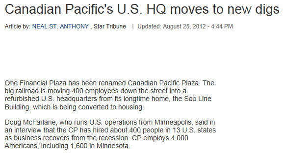
I'm looking for info on CP's (and anyone else's) operation centers!
Differences between US and British signal methods (Railway Technical Web Pages)
RAILFAN GUIDES HOME
RAILROAD SIGNALS HOME
New 10-6-2006
Last Modified:
26-Aug-2013