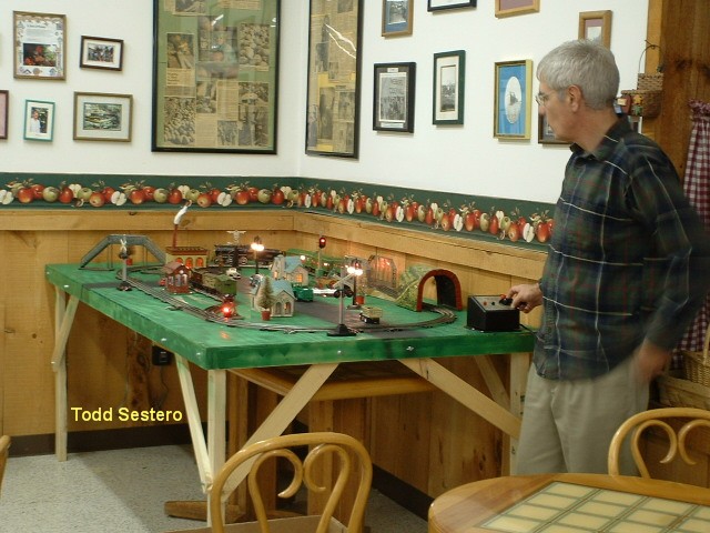
John Operating His As Yet, Unfinished 1920's Style Dorfan Train Layout
RAILROAD SIGNALS of the U.S.
SIMPLE
SIGNAL CIRCUIT
For A Two Color Red
and Green
Lionel Type Signal
RAILFAN GUIDES HOME
RAILROAD SIGNALS HOME
John Operating His As Yet, Unfinished 1920's
Style Dorfan Train Layout
Last week (OK, so it's been a few years by now), my best friend John called me up with a problem (it's nice to have these sort of problems!). He volunteered me to help him install a small Christmas train layout in a local garden store. The layout he was putting there was a mix of Dorfan trains and Lionel accessories. John is the only person I know that collects Dorfan stuff, I believe most of it is from the 20's and 30's.
He had one signal on the layout, and wanted it to stay red after the train passed it, and then turn green after it got about halfway around. If any of you are familiar with signals of the era, they were not complex, and operated off of simple track pick-ups (photos 1 and 2). Photo 1 is a single circuit pickup for controlling a single bulb, photo 2 is a dual pick-up, used for actuating (for example), a crossing signal with two lamps. The problem with these is that they only light the signal bulb when a wheel is going over the pickup. John wanted more.
 Photo 1 - Single Contact Pick-up
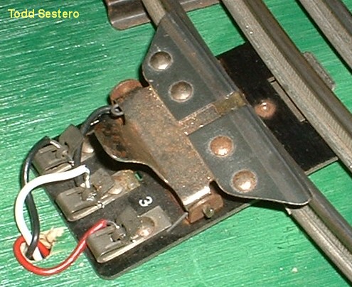 Photo 2 - Double Contact Pick-up
 Photo 2a - Lionel Crossing Signal
To some of you with a background in electronics, this circuit is no doubt - trivial. It may be a simple circuit, but it gave me an excuse to clean out some of my "junk-box", which now takes up more memory space than my basement has allotted. Somewhere, I knew I had seen a ridiculous latching relay arrangement (photo 3). The only problem with it was that the relays were 24VDC, and DC wasn't in train vocabulary when these things came out. So, I searched for a 24VDC power supply and came up with a +5V/+12V/-12V unit used to operate a commercial desk phone from Rolm (photo 4). Taking the output across the -12V and the +12V pins gives me my 24 volts, and I don't need to worry about the common connection between them. The power supply had a CAT-5 connector on it, which at first seems odd, but considering it was for a phone…..
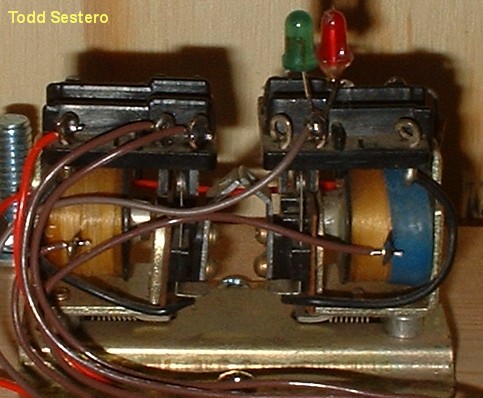 Photo 3 - Latching Relay
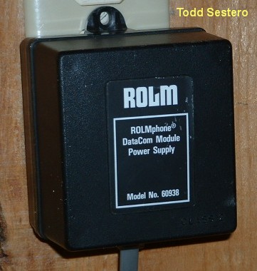 Photo 4 - The Power Supply
So I put everything together on a piece of wood, just like they "breadboarded" things back in those days, and used a pen to mark the terminals. It took me about 30 minutes to put everything together and solder it up. Later on, I added two LEDs to let John know if the relays were "picking" (operating, or pulling in). The inputs and outputs are brought out to a standard barrier type terminal strip. Classic simplicity. Photo 5 is the completed unit (sorry about the "fuzz"). Photo 6 is a shot of the signal with the train passing by.
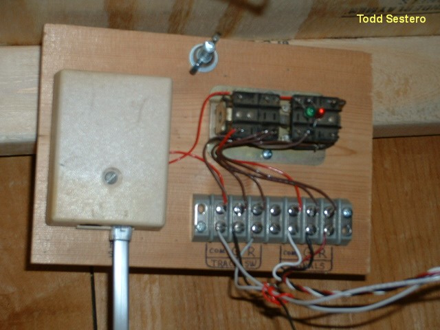 Photo 5 - The Completed Unit
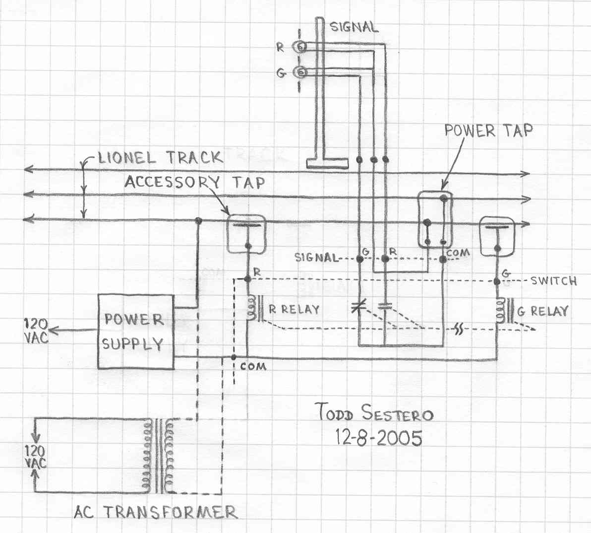
Operation is straightforward. Since I am using an isolated power supply (the source is not common to the track circuit operating the train), there is no problem or danger from interaction between the 24VDC and the train power pack. So I tie one side of the 24 volts to the outer track, the other side of the 24 volts goes to the "COM" switch input. The other side of each relay goes to one of the pick-ups, thru the "R" and "G" switch terminals. When the train rolls over the pick-ups, the wheels complete the circuit and pull in the appropriate relay. Because of the mechanical arrangement of the relays, one latches the other into place.
 Photo 6 - Signal With Passing Train
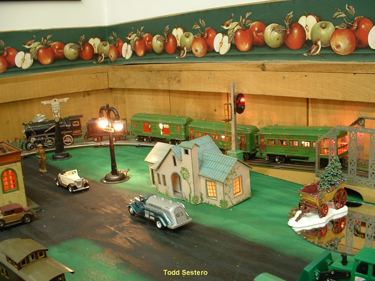 Photo 7 - Corner Of The Layout With The Signal
Although each relay has two sets of contacts, I only need one of the four sets to operate the signal. These contacts are brought out to the terminal strip. Again, since we decided to operate the signal off of track power, the "COM" signal terminal is connected to one of the rails of the track. The "R" and "G" signal terminals go to the corresponding lamp of the signal. The common terminal of the signal gets connected to the other rail. Refer to the schematic.
OK, so what can you do different? You can connect the lamp voltage circuit to the accessory output of your transformer if you have them available and want the signal(s) to stay on when the train is not running. You could also power the signal with a separate transformer altogether, such as a 12V filament transformer rated for at least an amp or so. Here again, the transformer for outdoor garden lights would do very well, and could also be used to power the lights for the whole layout (In case you haven't noticed from my other technical discussion on driving prototype signals, I'm a big fan of those transformers).
If you have the type of switch machine that uses two coils and has multiple contacts on it, you can use them too. Just remember that they usually operate on AC, so you could operate them directly off the track circuit. You could also operate them from the accessory output of the train's power pack, but this will tie the two outputs together. I'm not totally sure the outputs are isolated, I'm just guessing. If they are not, and one side IS common, you just have to pay attention to this fact when you are wiring up the circuit. If you use AC relays, you can substitute the transformer in the schematic, by connecting it as shown by the dotted lines.
NEW
10/6/2006
Last Modified:
05-Aug-2013