RAILROAD SIGNALS of the U.S.
PRIMER ON
AMERICAN RAILROAD SIGNALS
Reading And
Interpreting Railroad Signals 2
◄
PREVIOUS Chapter
![]() NEXT Chapter
►
NEXT Chapter
►
RAILFAN GUIDES HOME
RAILROAD SIGNALS HOME
CHAP 1 -
Introduction
CHAP 2 - Some Basic
Specs
CHAP 3
-
Glossary of Signal Terminology
CHAP 4
-
Reading And Interpreting
Railroad Signals 1
CHAP 5
-
Reading And Interpreting
Railroad Signals 2
Multiple Heads Why do we need more than one signal head, and what do they all mean?
Red as Place Holder A Simple Concept.
Darkened Heads Why the railroads would selectively turn off a signal head.
Staggered Heads and Absolute vs Permissive Why the railroads came up with this indication and it's impact on operations.
Stop Signals vs Grade Signs Another way a railroad can help to control costs.
Blanking out unused positions A simple way to control your inventory.
Signal Spacing How it changes the meaning of a signals indication.
Signal Bridges When you have more than one track to signal.
Doll Posts A placeholder for un-signaled tracks.
Backgrounds Helping with the visibility of a signal.
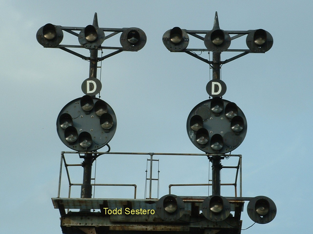
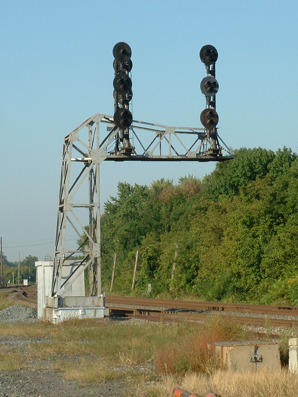
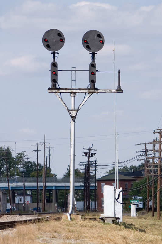
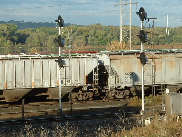 Railroads
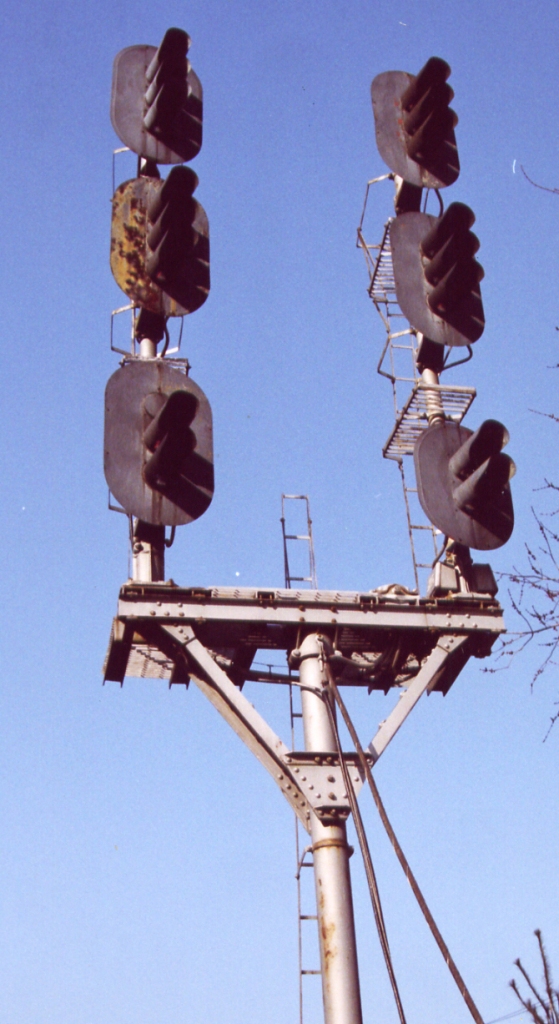
can normally use a single head signal for wayside signals, if the only purpose
is to tell the engineer the condition of the track ahead of him. If the
signal designer wishes to tell the engineer more, they add additional heads.
A single head is usually a high speed signal, meaning the the engineer is
allowed to go the maximum speed authorized by his handbook or timetable for that
particular section of track if he has a clear. The picture to the left is
on the south side of Pigs Eye yard in St Paul MN, and shows a pair of three head
searchlight signals.
Railroads
can normally use a single head signal for wayside signals, if the only purpose
is to tell the engineer the condition of the track ahead of him. If the
signal designer wishes to tell the engineer more, they add additional heads.
A single head is usually a high speed signal, meaning the the engineer is
allowed to go the maximum speed authorized by his handbook or timetable for that
particular section of track if he has a clear. The picture to the left is
on the south side of Pigs Eye yard in St Paul MN, and shows a pair of three head
searchlight signals.
![]()
![]() These excerpts are from a
Conrail
signal card dated 1988.
These excerpts are from a
Conrail
signal card dated 1988.
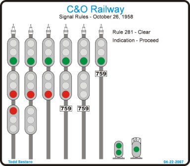
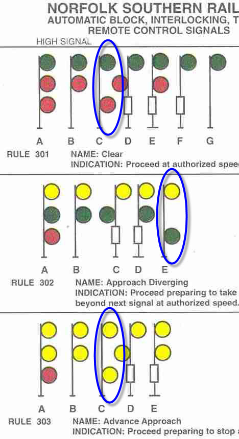
With the addition of more heads, the top head is the high speed head, the middle head is for medium speed moves, and the bottom head is for slow speed moves.
With a green on top, or G/R/R, as it is usually referred to, it authorizes the engineer to proceed at the maximum allowable speed for that section. Move the green down to the middle position, R/G/R, however, and the meaning changes. Now the indication is "medium clear", and the maximum allowable speed is (usually) around 30MPH. Bumping the green down to the bottom head, R/R/G, and the indication is now a "slow clear", and limits the trains speed to 15MPH.
So why do they want to control the speed of a train? For a variety of reasons: a move thru a set of crossovers, a move onto a siding, going onto a diverging route, bad track, workers present on the right-of-way, etc. Most, if not all rulebooks, state the the entire train has to pass through the switches, or pass the signal, before the train can resume a higher speed.
In addition to the colors of a signal, the meaning can also be modified by having the aspect flash. In almost all circumstances on railroads, a flashing aspect makes the signal more restrictive.
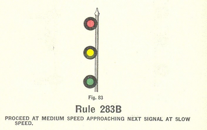 To
further complicate the interpretation of a signals meaning, railroads employed
multiple non-red aspects, such as Y/Y/R, which on many railroads would be an
"advance approach", sort of like having a distant semaphore giving you an
indication of the signal two signals away, allowing the engineer more time to
prepare for speed changes. The New York Central, for instance, employed a
R/Y/G signal, which stated the engineer had to proceed at medium speed,
approaching the next signal at slow speed, in other words, he could pass this
signal at medium speed, but had to reduce the speed of the train right away so
he wouldn't be going faster than 15MPH when he came upon the next signal - it
still really follows the medium and slow speed guide for the meaning of the
position of the heads.
To
further complicate the interpretation of a signals meaning, railroads employed
multiple non-red aspects, such as Y/Y/R, which on many railroads would be an
"advance approach", sort of like having a distant semaphore giving you an
indication of the signal two signals away, allowing the engineer more time to
prepare for speed changes. The New York Central, for instance, employed a
R/Y/G signal, which stated the engineer had to proceed at medium speed,
approaching the next signal at slow speed, in other words, he could pass this
signal at medium speed, but had to reduce the speed of the train right away so
he wouldn't be going faster than 15MPH when he came upon the next signal - it
still really follows the medium and slow speed guide for the meaning of the
position of the heads.
An excerpt from my New York Central aspect page.
The indication also has different meanings on whether the railroad employs route or speed signaling. In the SR example, a green in the middle would indicate a "diverging route clear", where the train can proceed thru the diverging route observing the authorized speed thru the crossover or turnout (which would be specified in the rulebook). On the old New York Central routes, a green in the middle would be a limited clear, limiting speed to 40 or 45MPH, not necessarily thru turnouts.
Old railroaders use the phrase "if it ain't all red, it ain't red at all", meaning any colors displayed in the signal other than red make the signal less restrictive than stop.
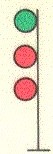
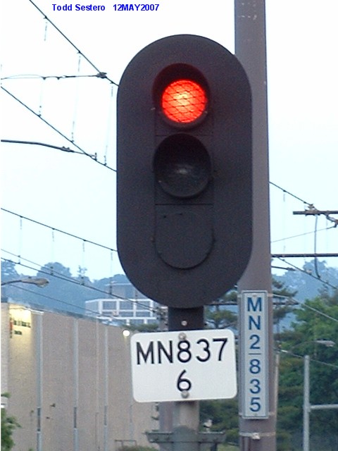
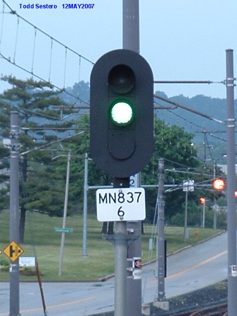
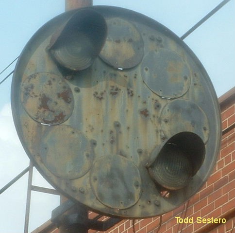
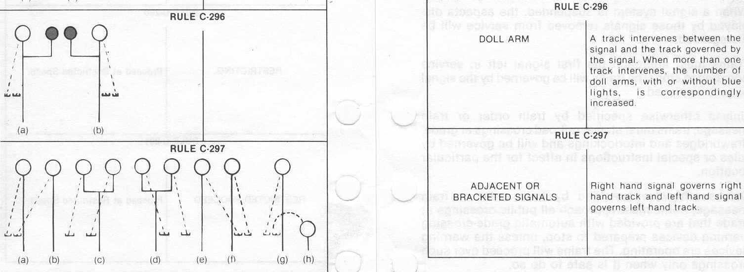
On multiple head signals, regardless of the type of signal used (color light, searchlight, etc), red is used as a placeholder. Take, for instance, a three head signal showing green over red over red (G/R/R). I can't think of a railroad that doesn't have this in their books as a clear signal. The plate to the left illustrates the concept as practiced on many railroads.
All of the signals pictured display the same indication, clear, regardless if there are 1, 2, or 3 heads.
This discussion also brings us around to the rule on most railroads that an improperly displayed signal is considered the most restricting aspect, mainly, stop.
The above example also illustrates another common practice of "darkening" the bottom signal, if it's not needed for the indication. With 2 or 3 head signal installations, they could choose not to light up the bottom head, where red is used just as a placeholder anyway.
This practice has fallen out of favor with the FRA, so it's
use it not as widespread as it used to be. This is because, on non-color
light installations, as with searchlight signals, a bulb could be out, and the
bottom head would then NOT be able to display a green or yellow. A lamp
out in a signal is considered a red, so, with a three head searchlight location
like the one at Pigs Eye at the left, the signal would not be able to display a R/R/G
or R/R/Y indication if the bottom bulb was out, and the engineer would have to
interpret the signal as a stop signal. There would be no way for the
engineer to know from looking at the signal if the bottom head was a red, or the
bulb was out and was supposed to be yellow or green, and would have to bring the
train to a stop if he only saw a R/R.
Staggering Signals:
Absolute vs Permissive.
AKA Stop vs Stop and Proceed
Under normal circumstances, an engineer approaching a Stop Signal would have to completely stop his train and wait until the signal became more favorable before proceeding. This is called an Absolute Signal. Some railroads call this "Stop and Stay" as opposed to just a Stop Signal.
In some places, the railroads decided they could have the train stop, and then proceed at a restricted speed, looking for anything that might cause an accident. This is called a Permissive Signal. Railroads came up with the idea to place a number plate below the signal to denote a Permissive Signal, but in the old days before reflector type signs, and good headlights, this posed a problem at night.
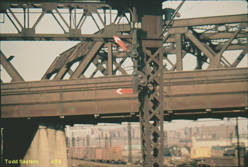
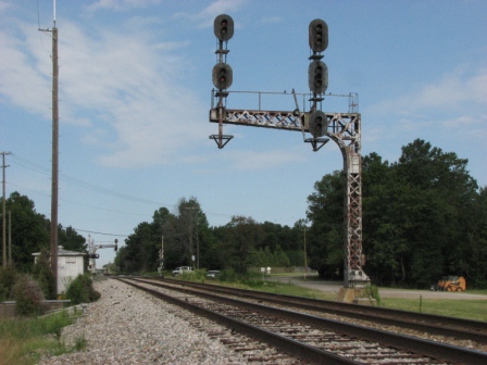
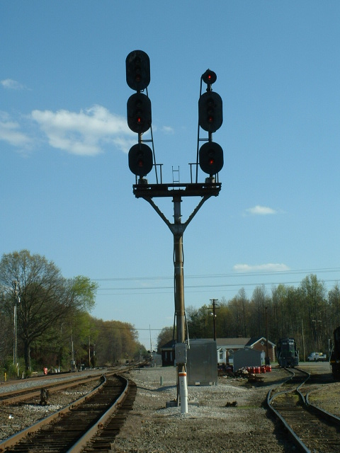
So how could the engineer tell at night if the signal he was approaching was a stop and proceed signal? The New York Central and New Haven, among others, staggered, or offset the lights, so at night, there was a visible difference in the appearance of the signal.
The left photo below is of a New Haven semaphore in the Bronx from back in the early 70's, and demonstrates how the upper signal is to the left of the mount, and the lower semaphore is to the right (Going back to a discussion in the semaphore section, each semaphore is it's own signal, in contrast to other forms of signals where multiple heads still are considered as "one signal").
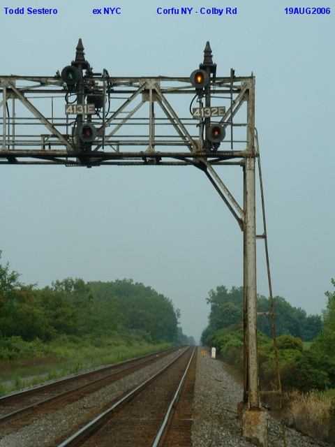
The photo in the middle is an example of this practice on the ex-NYC mainline between New York City and Buffalo, in Corfu NY. Notice that both signals also have a number plate displayed. The number plates and staggering of the signals only modified the meaning of the stop aspect, all other indications remained unaffected. The NYC shot also illustrates what AA Krug refers to in his discussion about the need for safety, where they didn't really need two heads, but used the extra head anyway. (look at he track ahead and you'll see there are no diverging routes, so one signal could have sufficed here). BTW, A little further down the track (westbound), where there are some crossovers, they do used three searchlight heads.
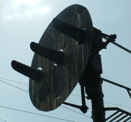
The right photo illustrates this practice in Gastonia NC on the former Southern Rwy.
Notice that the NYC and New Haven had the upper head offset to the left, and the Southern had it to the right.
Note that all three have number plates! It is fairly universal for numbered signals to be permissive. One exception was the Rio Grande, who numbered all of their signals. The DRGW called Absolute Signals Positive Signals, and used the letter "P" just above the number plate (Thanks to Mike McLaughlin on the Yahoo Signaling group for this tidbit of information in December of 2010).
As a recap, signals above one another in a straight line are absolute, signals that are staggered are permissive. Some railroads would also employ an "A Plate" to signify an absolute signal.
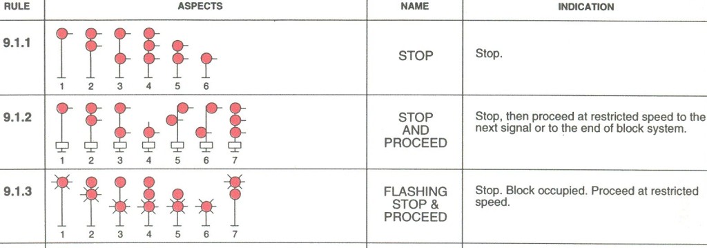
Below the photos is an excerpt from a CNW rulesheet out of a CORA manual. It shows a couple of things pertinent to our discussions.
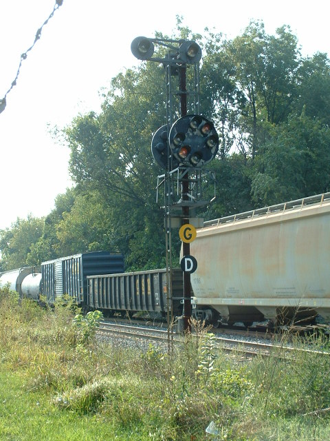
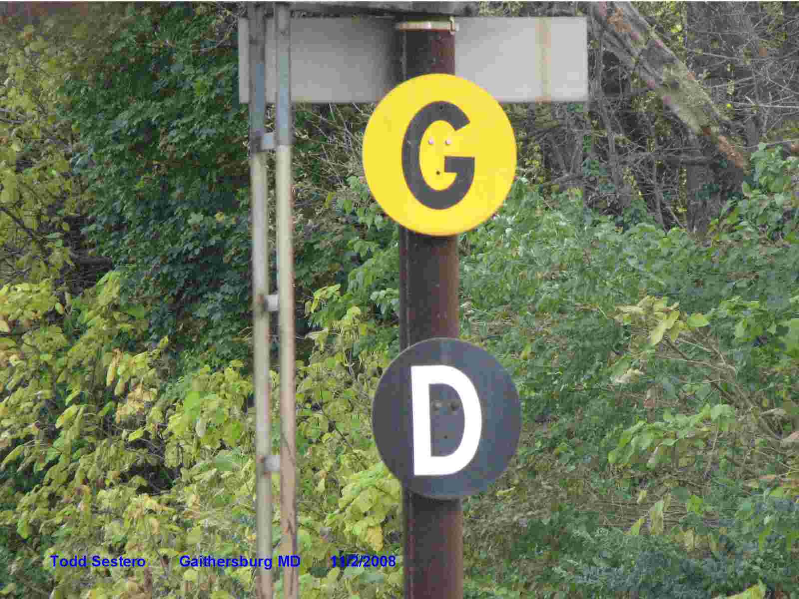
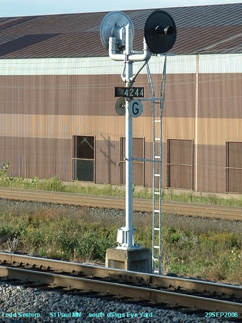
Railroads, in their ever clever ways to save even more money, came up with a modification to the stop rule for heavy tonnage trains on a grade, that would require a severe penalty in time and fuel to get the train moving again once given a more favorable indication, or braking distance if on a down grade. This was the grade sign. Heavy tonnage trains can roll by a stop signal at restricted speed if the signal has a grade sign displayed, usually as shown below in the two examples. The left and middle photos are of a CSX/ex-B&O grade sign on a CPL signal in Gaithersburg MD, and the one on the right is at the south end of Pigs Eye yard in St Paul MN, easily viewable from US10.
This practice is used when a signal head does not need all of the available aspects the head is capable of displaying.
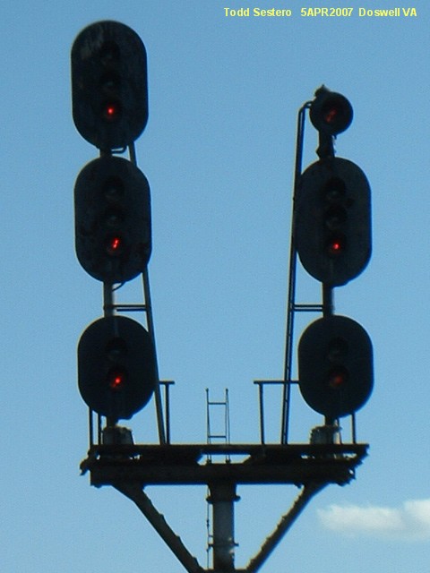
On most railroads, they would use an appropriately sized head, out of consideration for cost. If they only needed one or two aspects in a particular position, they would use a one or two position signal head, as shown to the left on the old RF&P line at Doswell VA. The right signal is only capable of displaying medium or slow speed indication since the top head is always red.
On the right, it shows the bottom head on the left having the green aspect being blanked out, but on the right, they use a two aspect head. Why? Maybe they downgraded the slow speed head so it could only give us a slow approach, and not a slow clear. Or maybe they ran out of two aspect heads.... Don't know from looking at the signal, but those are two possibilities. Notice that the bottom head on the left shows red in the middle position. Photo by Jim Mihalek.
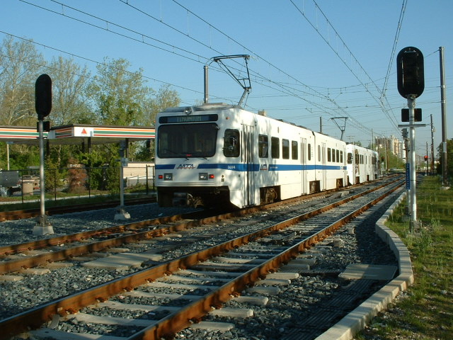
In other instances, such as many transit companies, they want to contain costs in a different way, so to keep different signal heads in stock, would cost more than the occasional use of blanking an aspect, as shown in the photos below at the Gilroy station on the Baltimore light rail, where the tracks goes from two to one for it's ride through the Hunt Valley Industrial Park.
Then there are the Pennsy PL and B&O CPL signal heads. The B&O did not have a "shortened" version of it's signal head like the Pennsy did for it's lower head. This meant they had to blank out all of the unused positions. The restrict only B&O signal (in S Baltimore) below shows this. The picture to the right shows a B&O signal (also in S Baltimore) with just the restrict aspect blanked out.
The middle picture shows a Pennsy PL head with just a stop aspect, with all of the other possibilities blanked out. The other two Pennsy signals other variations of blanking out unused positions. From left to right of the Pennsy pix, Columbia PA, Northumberland PA, and the west bank of the Rockville Bridge in Marysville PA.

Another way
the railroads saved money is illustrated to the left. This was to leave out the "middle" signal if they
had no medium speed moves at a particular location. An engineer could tell
that the lower head was a slow speed signal, by the larger than normal spacing
of the two sets of signals, although, since engineers have to qualify on
particular sections of track, the signals should not come as any great surpise.
Signal C for Clear, signal E for Approach Diverging, and signal C for Advance Approach are the signals of interest.
The scan on the left is from the Norfolk Southern rulebook for the Kentucky region.
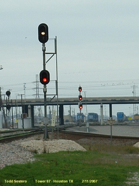
The photo below illustrates this practice. Compare the two signals in the picture, and you will notice the larger than normal spacing between signal heads, compared with the three head signal in the background. A train approaching the restrict signal would have just come through Tower 87 in Houston TX, headed into Settegast Yard. Depending on the indication the engineer receives next at the stop signal, he could get cleared to proceed into the yard, or take a diverging move to the left and head up to the Gulf Coast Junction.
If you have more than a single track, and need to signal them, what are your options?
You can put a full signal bridge over them....
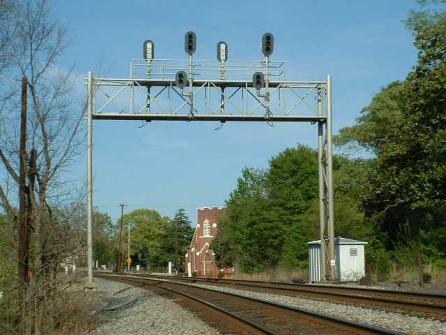 ex Southern Rwy, Gastonia NC
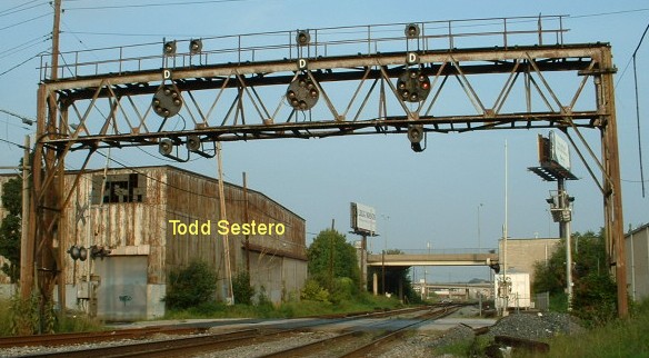 ex B&O, Ridgeley St, Baltimore MD
You can put a cantilever type signal bridge
over them (almost always limited to two tracks)...
(L) ex NYC, Berea OH, and (R) ex C&O, Richmond VA behind the airport.
The one in Berea has disappeared, replaced by color lights sometime in 2010.
You can put them on a bracket post..... again,
almost always limited to two tracks. See the
Doll Posts section for an unusual exception.
(L) ex B&O, South Baltimore MD... (M) ex RF&P, Doswel VA... (R) Color
Signal in Ohio (by Jim Mihalek)
Notice the RF&P signal has a siding between it and the tracks it governs.
BTW, the B&O CPL's are now gone, replaced in late 2012 by color lights.
Or, in a non-bridge application, you can put signals on both tracks:
 Baltimore Light Rail, Timonium MD
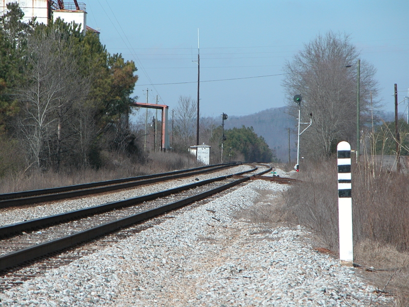
Now, what happens if you only need the left track (of two) signaled, but the only place you can put the signal is to the right of them? Enter the place holder, or Doll Post (some railroads refer to it as a Doll Arm). The picture below shows how the B&O did it with their CPL signals, this one is north on Baltimore at the end of a siding (hence the dwarf mounted to the bottom of the pole). The post, or arm to the right of the signal tells the engineer that there is a track to the right of the one that the signal is intended for.
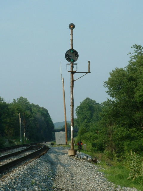
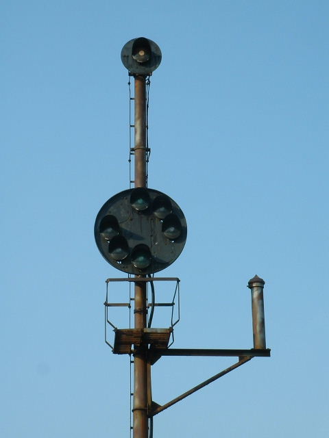
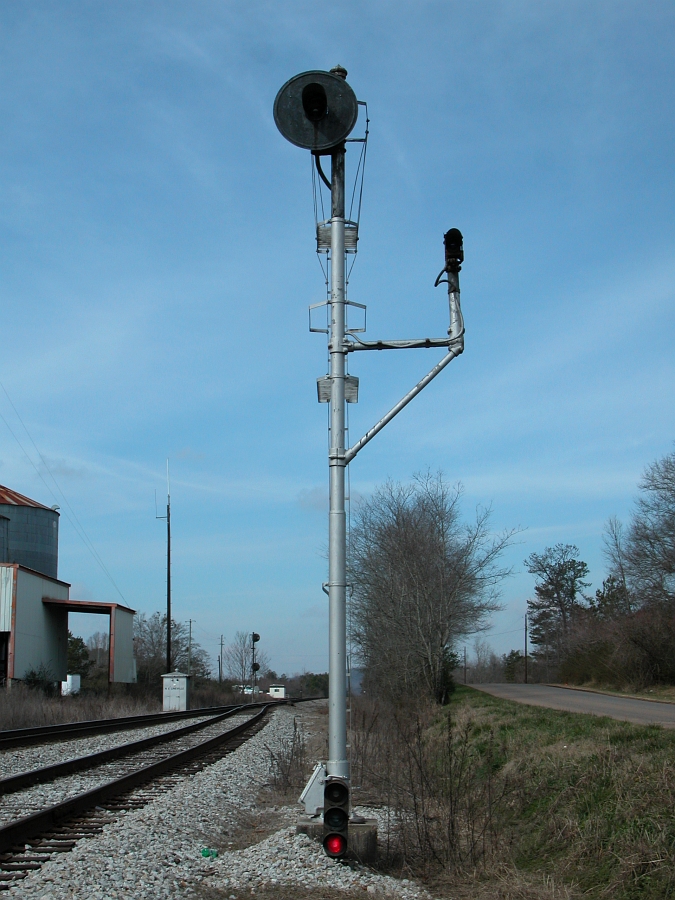
The second set of pictures of a US&S Searchlight signal with a doll post in Lineville AL on an ex-SCL line, As with many other railroads, they use a high signal for the mainline and a dwarf for the siding. Notice the blue doll post light is out. Photos courtesy John Higginson.
The last picture is of an ex N&W bracket installation where they have three tracks, and the right one is not signaled with a high signal. They mounted the doll post to an I-beam extension of the bracket. Photo by Jim Mahelik.
Below the pictures is an excerpt from a CSX rulebook that shows the possible combinations a doll post can appear, along with track assignments for bracketed signals.
The background of a signal is the metal shade that surrounds the entire signal or signal head. I have not seen the derivation for this term, but in looking at the old Tombstone signals on the Pennsylvania Railroad, I can clearly see that the background was a separate "device", and not part of the signal.
The main reason for using a background was to make the signal "stick out" when compared to the surrounding environment, especially if the sight line was anywhere near where the sun could be behind the signal. There are some places where backgrounds were not used, such as the lower head of some Pennsy PL signals. Some railroads also used wider than normal backgrounds, such as the Western Maryland, as shown below in Cumberland MD.
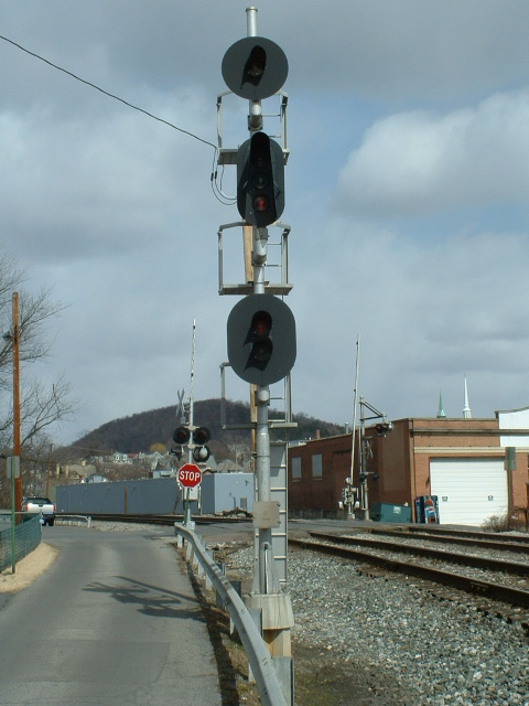
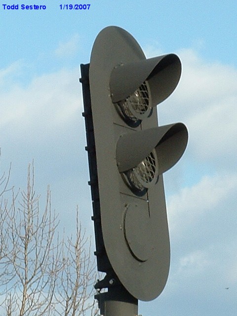
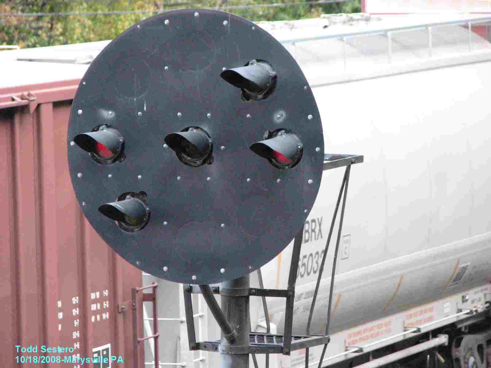
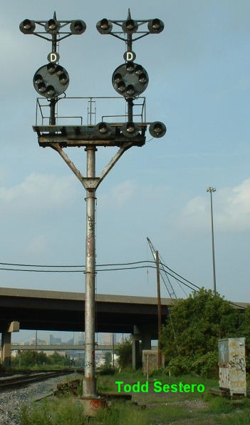
A call-on signal (oftentimes red over yellow, or red over red
over yellow) displays the *Restricting* indication, which is used for train
moves into unsignaled track, against the current of traffic, or into
occupied blocks. The latter scenario is the one that gives the "call-on"
name. It is "calling a train on[ward]" into an occupied block.
MKT in Texas used a double headed searchlight on their lines... The top head is
the larger while the bottom head is smaller. Top head had the H-5mechanism while
the bottom heads were ALL fixed yellow aspect. Every single lower head was a
fixed yellow. I have heard these were "call-on" signals.
Thu, Apr 11, 2013
◄
PREVIOUS Chapter
![]() NEXT Chapter
►
NEXT Chapter
►
NEW 12/29/2009
Last Modified:
26-Aug-2013